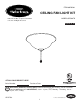
ITEM #0745341 CEILING FAN LIGHT KIT MODEL #EC901TA Harbor Breeze® is a registered trademark of LF, LLC. All Rights Reserved. Español p. 10 ATTACH YOUR RECEIPT HERE Serial Number Purchase Date E108082 Questions, problems, missing parts? Before returning to your retailer, call our customer service department at 1-800-643-0067, 8 a.m. - 6 p.m., EST, Monday - Thursday, 8 a.m. 5 p.m., EST, Friday. AB15789 Lowes.
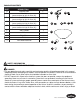
PACKAGE CONTENTS PART DESCRIPTION QUANTITY A Light Kit Fitter 1 B Hex Nut (preassembled to light kit fitter (A)) Lock Washer (preassembled to light kit fitter (A)) Flat Washer (preassembled to light kit fitter (A)) Small Rubber Washer (preassembled to light kit fitter (A)) 2 F Glass Shade 1 G Bulb 2 H Finial Plate 2 I Finial 2 J Pull Chain Extension 1 C D E A B 2 1 C E D 1 F G I H J SAFETY INFORMATION READ AND SAVE THESE INSTRUCTIONS.
SAFETY INFORMATION DANGER • DO NOT connect the bare or green insulation fixture ground wire to the black (HOT) current-carrying wire or the white neutral house wire. Connection of the bare or green fixture ground wire to the black or white house wires may cause metal parts of the fixture to carry electrical currents. Under this condition, anyone coming in contact with the fixture will receive electrical shock, which could cause serious injury or death.
SAFETY INFORMATION CAUTION • To reduce the risk of fire or electric shock, this light kit fitter (A) should only be used with the compatible ceiling fan models (sold separately) listed below: Aircool B-336, -442T, -452L, -536, -542, -552, -552A, -552H, -552L, -652, -652A, -652H, -652L, -736, -742, 852 (May or may not be followed by the suffix letter A, L or T.) PREPARATION Before beginning assembly of product, make sure all parts are present.
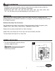
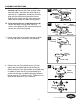
ASSEMBLY INSTRUCTIONS 2a. If the existing fan doesn't have a switch housing cap, remove the three existing switch housing screws and lower the switch housing from the fan. If applicable, disconnect the male plug from the motor housing and the female plug from the switch housing, then remove the switch housing from the switch housing plate. 2a 2b.
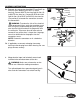
ASSEMBLY INSTRUCTIONS 5a. Remove wire connectors from WHITE and BLUE (or BLACK) wires labeled FOR LIGHT in switch housing. Connect WHITE wire from light kit fitter (A) to WHITE wire from fan. Connect BLACK wire from light kit fitter (A) to BLUE (or BLACK) wire from fan. Use previously removed wire connectors to make the connections.
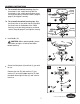
ASSEMBLY INSTRUCTIONS 7a. To re-install the switch housing, align the three holes in the switch housing with the three holes in the switch housing plate. Insert the three previously removed screws (Step 2a, page 5) and tighten securely. 7a Switch Housing Plate Switch Housing A 7b. To re-install the switch housing cap, align the three holes in the switch housing cap with the three holes in the bottom of the switch housing. Insert the three previously removed screws (Step 2b, page 5) and tighten securely.
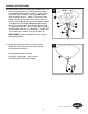
ASSEMBLY INSTRUCTIONS 10. Remove pull chain extension from fan pull chain if you have not already done so. Slide pull chain through corresponding hole in glass shade (F). Align center hole in the glass shade (F) with threaded rod and push up gently on glass shade (F). Re-install small rubber washer (E), flat washer (D), lock washer (C) and hex nut (B) previously removed in Step 9, page 7. Thread pull chain through appropriate hole in finial plate (H) and center pull chain through hole in finial (I).
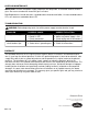
CARE AND MAINTENANCE IMPORTANT: Shut off main power supply. Wipe with soft damp cloth. Use window cleaner to clean glass. Do not use an abrasive cleaner on glass or fixture. Bulb Replacement: Use 60-watt max. candelabra-base incandescent bulbs, 13-watt candelabra-base CFLs or 6-watt max candelabra-base LED. TROUBLESHOOTING WARNING: Before beginning work, shut off the power supply to avoid electrical shock. PROBLEM Bulb(s) will not light. POSSIBLE CAUSE 1. Bulb(s) is/are burned out. 2. Power is OFF. 3.