ITEM #1100336 CEILING FAN LIGHT KIT MODEL #LED-WNWZ Español p. 10 ATTACH YOUR RECEIPT HERE Purchase Date Questions, problems, missing parts? Before returning to your retailer, call our customer service department at 1-800-643-0067, 8 a.m. - 6 p.m., EST, Monday - Thursday, 8 a.m. 5 p.m., EST, Friday.
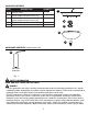
PACKAGE CONTENTS PART A B C D E DESCRIPTION QUANTITY Light Kit Fitter Hex Nut (preassembled to light kit fitter (A)) Lock Washer (preassembled to light kit fitter (A)) Glass Shade Bulb 1 1 A 1 B 1 2 C D E HARDWARE CONTENTS (shown actual size) AA Pull Chain Extension Qty. 1 SAFETY INFORMATION READ AND SAVE THESE INSTRUCTIONS.
SAFETY INFORMATION DANGER • DO NOT connect the bare or green insulation fixture ground wire to the black (HOT) current-carrying wire or the white neutral house wire. Connection of the bare or green fixture ground wire to the black or white house wires may cause metal parts of the fixture to carry electrical currents. Under this condition, anyone coming in contact with the fixture will receive electrical shock, which could cause serious injury or death.
SAFETY INFORMATION CAUTION • If you are not sure the lighting system has a grounding means, DO NOT attempt to install this fixture. Contact a qualified, licensed electrician for information regarding the proper grounding methods as required by the local electrical code in your area. • All fixtures must be mounted to a ceiling fan that is mounted to an outlet box supported by the building structure. • DO NOT use bulbs having a wattage greater than the maximum value stated on the fixture.
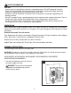
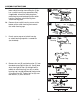
ASSEMBLY INSTRUCTIONS 2a. Remove three switch housing screws and lower switch housing from ceiling fan. [If fan has a switch housing cap, proceed to 2b.] If applicable, disconnect male plug from motor housing and female plug from switch housing. Remove switch housing from switch housing plate. 2b. Remove three switch housing screws at the bottom of the switch housing and remove the switch housing cap. 2a Motor Housing Switch Housing Plate Switch Housing 2b Motor Housing Switch Housing Cap 3.
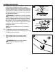
ASSEMBLY INSTRUCTIONS 5a. Remove wire connectors from WHITE and BLUE (or BLACK) wires labeled FOR LIGHT in switch housing. Connect WHITE wire from light kit fitter (A) to WHITE wire from fan. Connect BLACK wire from light kit fitter (A) to BLUE (or BLACK) wire from fan. Use wire connectors that were previously removed to make the connections.
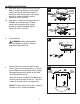
ASSEMBLY INSTRUCTIONS 7a. Align three holes in switch housing with three holes in switch housing plate. [To re-attach switch housing cap, proceed to Step 7b.] Re-attach switch housing with three screws previously removed (Step 2a, page 5). Tighten all screws securely. 6 7a 6 Switch Housing Plate Switch Housing A 7b. Align holes in switch housing cap with holes at bottom of switch housing. Re-attach switch housing cap with three screws previously removed (Step 2b, page 5). Tighten all screws securely.
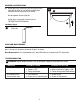
ASSEMBLY INSTRUCTIONS 10. Attach pull chain extension (AA) to light pull chain from light kit fitter (A). Re-attach fan pull chain extension that was previously removed. 10 A Restore power and test light kit. If light does not function, please refer to TROUBLESHOOTING below. AA Hardware Used AA Pull Chain Extension x 1 CARE AND MAINTENANCE IMPORTANT: Shut off main power supply. Wipe with soft damp cloth. Use window cleaner to clean glass. Do not use an abrasive cleaner on glass or fixture.
WARRANTY The distributor warrants all of its lighting fixtures against defects in materials and workmanship for one (1) year from the date of purchase. If within this period the product is found to be defective, take a copy of the bill of sale as a proof of purchase and the product in its original carton to the place of purchase. The distributor will, at its option, repair, replace or refund the purchase price to the consumer.