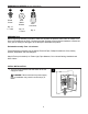
ITEM #2599768 RAYNERIDGE LED CEILING FAN MODEL #MH52MBK5LR Harbor Breeze® is a registered trademark of LF, LLC. All Rights Reserved. Español p. 19 ATTACH YOUR RECEIPT HERE Purchase Date Questions, problems, missing parts? Before returning to your retailer, call our customer service department at 1-800-643-0067, 8 a.m. - 8 p.m., EST, Monday - Sunday.
TABLE OF CONTENTS Safety Information ................................................................................................................. 2 Package Contents ................................................................................................................ 4 Hardware Contents ........................................................................................................................... 5 Preparation .......................................................................
SAFETY INFORMATION WARNING To reduce the risk of fire, electrical shock or personal injury, mount fan to outlet box marked "ACCEPTABLE FOR FAN SUPPORT OF 35 LBS. OR LESS" and use mounting screws provided with the outlet box. Most outlet boxes commonly used for the support of lighting fixtures are not acceptable for fan support and may need to be replaced. Consult a qualified electrician if in doubt. To avoid personal injury, the use of gloves may be necessary while handling fan parts with sharp edges.
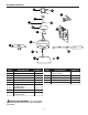
PACKAGE CONTENTS C G N A L M B O E D H I J K F PART A B C D E F G H I J DESCRIPTION Downrod Canopy Mounting Bracket Motor Housing Yoke Cover LED Light Kit Canopy Mounting Screw (preassembled) Light Kit Fitter Blade Motor Plate Screw (preassembled) PART DESCRIPTION K Light Kit Fitter Screw (preassembled) L Pin (preassembled) M Clip (preassembled) N Remote Control Receiver O Remote Pack QUANTITY 1 1 1 1 1 1 4 1 5 3 IMPORTANT REMINDER: You must use the parts provided with this fan for proper insta
HARDWARE CONTENTS (shown actual size) AA BB Blade Screw Fiber Blade Washer Qty. 15 + 1 extra Qty. 15 + 1 extra CC CC Wire Connector Qty. 4 PREPARATION Before beginning assembly of product, make sure all parts are present. Place motor on carpet or on foam to avoid damage to finish. Compare parts with package contents list and hardware contents list. If any part is missing or damaged, do not attempt to assemble the product.
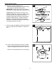
INITIAL INSTALLATION 2. Determine mounting method to use. A. Downrod mount (standard or angled ceiling) B. Closemount (standard ceiling only) IMPORTANT: If using the angle mount, check to make sure the ceiling angle is not steeper than 19°. 2 19° max. *Helpful Hint: Downrod-style mounting is best suited for ceilings 8 ft. or higher. For taller ceilings you may want to use a longer downrod (not included). Angle-style mounting is best suited for angled or vaulted ceilings.
INITIAL INSTALLATION 4b. Secure mounting bracket (C) to outlet box (not included) using screws, spring washers and flat washers provided with the outlet box. 4b *NOTE: It is very important you use the proper hardware when installing the mounting bracket (C) as this will support the fan. ANGLE MOUNT STANDARD MOUNT C IMPORTANT: If using the angle mount, make sure open end of mounting bracket (C) is installed facing the higher point of the ceiling, and ensure the ceiling angle is not steeper than 19°.
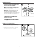
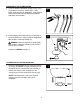
DOWNROD-STYLE FAN MOUNTING 2. Insert downrod (A) through canopy (B), and yoke cover (E). Thread wires from motor housing (D) up through downrod (A). 2 A B E 3. Slip downrod (A) into yoke, align holes and re-install pin (L) and clip (M). Tighten downrod (A) set screws and then tighten nuts. Slide yoke cover (E) down until it rests on top of motor housing (D). 3 E A M Set Screw and Nut L D 4. Depending on the length of downrod you use, you may need to cut the lead wires back to simplify the wiring.
DOWNROD-STYLE FAN MOUNTING 5. If you cut back the lead wires in Step 4, strip 1/2 in. of insulation from end of of each wire -- white, black, green and blue (if applicable). Twist stripped ends of each strand of wire within the insulation with pliers (not included). 6. Install hanging ball of downrod (A) into opening of mounting bracket (C). Align the slot in hanging ball with the tab in mounting bracket (C).
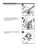
CLOSEMOUNT-STYLE FAN MOUNTING 2. Remove every other preassembled screw and lock washer from top of motor housing (D). 2 Screw Lock Washer D 3. Pull wires up through hole in the middle of the canopy (B) and attach canopy (B) to motor housing (D) using the three previously removed screws and lock washers. 3 Screw Lock Washer B D 4. Temporarily hang fan on the tab on the mounting bracket (C) using one of the non-slotted holes in the canopy (B).
WIRING WARNING: To reduce the risk of fire, electrical shock or personal injury, wire connectors provided with this fan are designed to accept only one 12-gauge house wire and two lead wires from the fan. If your house wire is larger than 12-gauge or there is more than one house wire to connect to the corresponding fan lead wires, consult an electrician for the proper size wire connectors to use. CAUTION: Be sure outlet box is properly grounded and that a ground (green or bare) wire is present.
WIRING 2. Wrap electrical tape (not included) around each individual wire connector (CC) down to the wire. 2 WARNING: Make sure no bare wire or wire strands are visible after making connections. Place GREEN and WHITE wire connections on the opposite side of the outlet box from the BLACK and BLUE wire connections. CC CC Turn spliced/taped wires upward and gently push wires and wire connectors (CC) into outlet box. 3. Gently slide remote control receiver (N) flat-side up into mounting bracket (C).
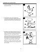
FINAL INSTALLATION 2. DANGER: To reduce the risk of serious bodily injury, DO NOT use power tools to assemble the blades (I). If screws are overtightened, blades (I) may crack and break. 3 2 D Insert the blade (I) through the slot on the band of the motor housing (D). Align holes in blade (I) with holes in plate on underside of motor. Attach the blade (I) with blade screws (AA) and fiber blade washers (BB). Then, tighten each blade screw (AA), starting with the one in the middle.
FINAL INSTALLATION 5. Locate BLUE and WHITE wires in light kit fitter (H). Connect WHITE wire from LED light kit (F) to WHITE wire from light kit fitter (H). Connect BLACK wire from LED light kit (F) to BLUE wire from light kit fitter (H). Make sure molex connections are secure. 3 5 H WHITE Carefully arrange wires inside light kit fitter (H). Align holes in LED light kit (F) with posts in light kit fitter (H). Re-insert light kit fitter screws (K) previously removed (step 4, page 13).
OPERATING INSTRUCTIONS CAUTION: “DO NOT DISPOSE OF BATTERIES IN FIRE, BATTERIES MAY EXPLODE OR LEAK.” - When disposing of household alkaline batteries, it is best to check with your local and state recycling or household hazardous waste coordinators concerning the specifics of the program in your area. You may also locate a recycling center by calling 1-800-8-BATTERY or 1-877-2-RECYCLE or visit www.epa.gov/epawaste/index.htm or www.earth911.org for more information.
OPERATING INSTRUCTIONS 3a. In warmer weather, setting the reverse switch in the LEFT position will result in downward airflow creating a wind chill effect. 3a 3b 3b. In cooler weather, setting the reverse switch in the RIGHT position will result in upward airflow that can help move stagnant, hot air off the ceiling area. 3c. IMPORTANT: Reverse switch must be set either completely LEFT or completely RIGHT for fan to function. If the reverse switch is set in the middle position, fan will not operate.
TROUBLESHOOTING WARNING: Before beginning work, shut off the power supply to avoid electrical shock. PROBLEM Fan does not move. POSSIBLE CAUSE 1. Reverse switch not engaged. 2. Power is off or fuse is blown. 3. Faulty wire connection. 4. Wires in light kit fitter not wired correctly. Noisy operation. 1. Blades are loose. 2. Cracked blade. 3. Full range dimmer switch. 4. Fan is new. Excessive wobbling. 1. Blades are loose. 2. Unbalanced blades. 3. Fan not securely mounted. 4.
LIMITED LIFETIME WARRANTY The distributor warrants this fan to be free from defects in workmanship and materials present at time of shipment from the factory for Lifetime limited from the date of purchase. This warranty applies only to the original purchaser. The distributor agrees to correct any defect at no charge or, at our option, replace the ceiling fan with a comparable or superior model. To obtain warranty service, present a copy of your sales receipt as proof of purchase.