Table of Contents Safety ......................................................... 3 Specifications ............................................. 8 Setup .......................................................... 8 Operation .................................................... 9 Maintenance .............................................. 12 Parts List and Diagram .............................. 14 Warranty ....................................................
IMPORTANT SAFETY INFORMATION 1. Wear ANSI-approved safety goggles and heavy-duty work gloves during use. 2. Keep work area clean and well lit. 3. Keep bystanders out of the area during use. 4. Do not use when tired or when under the influence of alcohol, drugs or medication. 5. This product is not a toy. Do not allow children to play with or near this item. 6. Use as intended only. Do not use handle extension to increase force. 7. Inspect before every use; do not use if parts are loose or damaged. 8.
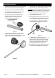
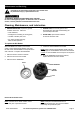
Operating Instructions 1. Assemble the Handle Rod parts and insert threaded portion of Handle Tube into the Ratchet Holder. 6. Fill an Oil Can with Thread Cutting Oil (not included). Keep it nearby during the threading operation. 2. Determine the size of the pipe to be threaded. CAUTION: Make sure the pipe end and threads of the Die are sufficiently oiled at all times. Otherwise, Die life will be shortened and the threads will be rough. 3. Pick the appropriate Die to be used.
Maintenance and Servicing Procedures not specifically explained in this manual must be performed only by a qualified technician. TO PREVENT SERIOUS INJURY FROM TOOL FAILURE: Do not use damaged equipment. If abnormal noise or vibration occurs, have the problem corrected before further use. Cleaning, Maintenance, and Lubrication 1. BEFORE EACH USE, inspect the general condition of the tool. Check for: • loose hardware, • misalignment or binding of moving parts, • cracked or broken parts, and 2.
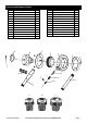
Parts List and Diagram (62353) Part 1A 2A 3A 4A 1B 2B 3B 4B 1C 2C 3C 4C 1D 2D 3D 4D 1E 2E 3E 4E 1F Description 3/8" Die Screw 3/8" Die Cover 3/8" Die Ratchet Coupling 3/8" Die Blade Set 1/2" Die Screw 1/2" Die Cover 1/2" Die Ratchet Coupling 1/2" Die Blade Set 3/4" Die Screw 3/4" Die Cover 3/4" Die Ratchet Coupling 3/4" Die Die Blade Set 1" Die Screw 1" Die Cover 1" Die Ratchet Coupling 1" Die Blade Set 1-1/4" Die Screw 1-1/4" Die Cover 1-1/4" Die Ratchet Coupling 1-1/4" Die Blade Set 1-1/2" Die Screw 2A
Parts List and Diagram (62354) Part 1A 2A 3A 4A 1B 2B 3B 4B 1C 2C 3C 4C Description 1/2" Die Screw 1/2" Die Cover 1/2" Die Ratchet Coupling 1/2" Die Blade Set 3/4" Die Screw 3/4" Die Cover 3/4" Die Ratchet Coupling 3/4" Die Blade Set 1" Die Screw 1" Die Cover 1" Die Ratchet Coupling 1" Die Blade Set 2A-C 1A-C 4A-C Qty 4 1 1 4 4 1 1 4 4 1 1 4 2 3 5 6 7 8 9 10 11 12 13 14 15 5 3A-C 1 Part Description Qty Plate Ratchet Ratchet Holder Plate Screw Handle Tube Pawl Spring Knob Pin Handle 6 7 1
PLEASE READ THE FOLLOWING CAREFULLY THE MANUFACTURER AND/OR DISTRIBUTOR HAS PROVIDED THE PARTS LIST AND ASSEMBLY DIAGRAM IN THIS DOCUMENT AS A REFERENCE TOOL ONLY. NEITHER THE MANUFACTURER OR DISTRIBUTOR MAKES ANY REPRESENTATION OR WARRANTY OF ANY KIND TO THE BUYER THAT HE OR SHE IS QUALIFIED TO MAKE ANY REPAIRS TO THE PRODUCT, OR THAT HE OR SHE IS QUALIFIED TO REPLACE ANY PARTS OF THE PRODUCT.