Table of contents SAFETY Safety ......................................................... 2 Specifications ............................................. 8 Setup .......................................................... 9 Operation ................................................... 10 Maintenance .............................................. 12 Parts List and Diagram .............................. 14 Warranty ....................................................
1. power tool plugs must match the outlet. Never modify the plug in any way. Do not use any adapter plugs with grounded power tools. Unmodified plugs and matching outlets will reduce risk of electric shock. 4. Do not abuse the cord. Never use the cord for carrying, pulling or unplugging the power tool. Keep cord away from heat, oil, sharp edges or moving parts. Damaged or entangled cords increase the risk of electric shock. 2.
7. Use the power tool, accessories and tool bits etc. in accordance with these instructions, taking into account the working conditions and the work to be performed. Use of the power tool for operations different from those intended could result in a hazardous situation. SAFETY Service Have your power tool serviced by a qualified repair person using only identical replacement parts. This will ensure that the safety of the power tool is maintained. Drill Safety Warnings 1.
Vibration Safety 1. Anyone using vibrating tools regularly or for an extended period should first be examined by a doctor and then have regular medical check-ups to ensure medical problems are not being caused or worsened from use. Pregnant women or people who have impaired blood circulation to the hand, past hand injuries, nervous system disorders, diabetes, or Raynaud’s Disease should not use this tool.
Grounding SAFETY TO pREVENT ELEcTRIc SHOcK AND DEATH FROM INcORREcT GROUNDING WIRE cONNEcTION: check with a qualified electrician if you are in doubt as to whether the outlet is properly grounded. Do not modify the power cord plug provided with the tool. Never remove the grounding prong from the plug. Do not use the tool if the power cord or plug is damaged. If damaged, have it repaired by a service facility before use.
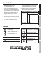
2. As the distance from the supply outlet increases, you must use a heavier gauge extension cord. Using extension cords with inadequately sized wire causes a serious drop in voltage, resulting in loss of power and possible tool damage. (See Table A.) 3. The smaller the gauge number of the wire, the greater the capacity of the cord. For example, a 14 gauge cord can carry a higher current than a 16 gauge cord. (See Table A.) 4.
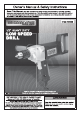
Specifications SAFETY Electrical Rating 120 V~ / 60 Hz / 7.5 A Motor No Load Speed 0 - 550 RPM Chuck Capacity 1/16″ to 1/2″ 95GA E194601 SETUp OpERATION MAINTENANcE REV 09l Page 8 For technical questions, please call 1-800-444-3353.
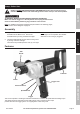
Setup - Before Use: SAFETY Read the ENTIRE IMpORTANT SAFETY INFORMATION section at the beginning of this manual including all text under subheadings therein before set up or use of this product. TO pREVENT SERIOUS INJURY FROM AccIDENTAL OpERATION: Make sure that the Trigger is in the off-position and unplug the tool from its electrical outlet before performing any procedure in this section.
Operating Instructions Read the ENTIRE IMpORTANT SAFETY INFORMATION section at the beginning of this manual including all text under subheadings therein before set up or use of this product. SAFETY Tool Set Up TO pREVENT SERIOUS INJURY FROM AccIDENTAL OpERATION: Make sure that the Trigger is in the off-position and unplug the tool from its electrical outlet before performing any procedure in this section.
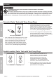
1. Make sure that the Trigger is in the off-position, then plug in the tool. 2. Use the Forward/Reverse Switch above the Trigger to determine the rotation direction of the Chuck. Slide it to the right side for clockwise Chuck rotation. Slide to the left side for counterclockwise Chuck rotation. 3. cAUTION! Do not change direction while the drill is operating. Allow chuck to come to complete stop prior to changing its direction of rotation. 4. Squeeze the Trigger to start the tool.
Maintenance and Servicing procedures not specifically explained in this manual must be performed only by a qualified technician. SAFETY TO pREVENT SERIOUS INJURY FROM AccIDENTAL OpERATION: Make sure that the Trigger is in the off-position and unplug the tool from its electrical outlet before performing any procedure in this section. TO pREVENT SERIOUS INJURY FROM TOOL FAILURE: Do not use damaged equipment. If abnormal noise or vibration occurs, have the problem corrected before further use.
Troubleshooting 1. Cord not connected. 1. Check that cord is plugged in. 2. No power at outlet. 2. Check power at outlet. If outlet is unpowered, turn off tool and check circuit breaker. If breaker is tripped, make sure circuit is right capacity for tool and circuit has no other loads. 3. Tool’s thermal reset breaker tripped (if equipped). 3. Turn off tool and allow to cool. Press reset button on tool. 4. Internal damage or wear. (Carbon brushes or Trigger, for example.) 4.
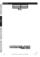
parts List and Diagram pLEASE READ THE FOLLOWING cAREFULLY SAFETY THE MANUFACTURER AND/OR DISTRIBUTOR HAS PROVIDED THE PARTS LIST AND ASSEMBLY DIAGRAM IN THIS MANUAL AS A REFERENCE TOOL ONLY. NEITHER THE MANUFACTURER OR DISTRIBUTOR MAKES ANY REPRESENTATION OR WARRANTY OF ANY KIND TO THE BUYER THAT HE OR SHE IS QUALIFIED TO MAKE ANY REPAIRS TO THE PRODUCT, OR THAT HE OR SHE IS QUALIFIED TO REPLACE ANY PARTS OF THE PRODUCT.
MAINTENANcE OpERATION SETUp SAFETY Assembly Diagram Item 93632 For technical questions, please call 1-800-444-3353.
Limited 90 Day Warranty Harbor Freight Tools Co. makes every effort to assure that its products meet high quality and durability standards, and warrants to the original purchaser that this product is free from defects in materials and workmanship for the period of 90 days from the date of purchase.