0,000 PSI AIR/Hydraulic Foot Pump Model 98318 Set up and Operating Instructions Diagrams within this manual may not be drawn proportionally. Due to continuing improvements, actual product may differ slightly from the product described herein. Distributed exclusively by Harbor Freight Tools®. 3491 Mission Oaks Blvd., Camarillo, CA 93011 Visit our website at: http://www.harborfreight.com Read this material before using this product. Failure to do so can result in serious injury. Save this manual.
Save This Manual NOTICE is used to address practices not related to personal injury. Keep this manual for the safety warnings and precautions, assembly, operating, inspection, maintenance and cleaning procedures. Write the product’s serial number in the back of the manual near the assembly diagram (or month and year of purchase if product has no number). Keep this manual and the receipt in a safe and dry place for future reference.
tool while tired or under the influence of drugs, alcohol, or medication. A moment of inattention while operating tool increases risk of injury. b. Dress properly. Do not wear loose clothing or jewelry. Contain long hair. Keep hair, clothing, and gloves away from moving parts. Loose clothes, jewelry, or long hair increases risk of injury to as result of being caught in moving parts. c. Avoid unintentional starting. Be sure the switch is off before connecting to the air supply.
the specific tool model. Use of an accessory not intended for use with the specific tool model, increases the risk of injury to persons. Service a. Tool service must be performed only by qualified repair personnel. b. When servicing a tool, use only identical replacement parts. Use only authorized parts. c. b. Symbol Definitions Symbol no .../min Use only the lubricants supplied with the tool or specified by the manufacturer. Air source a.
2. 3. Do not adjust the factory set Safety Valve. This valve should only be set or reset by a qualified technician. This air hydraulic Foot Pump must be secured tightly to a stable surface to prevent dynamic pressure from moving it around during use. Make sure there is no tripping hazard. Vibration Precautions This tool vibrates during use. Repeated or long-term exposure to vibration may cause temporary or permanent physical injury, particularly to the hands, arms and shoulders.
Save these instructions. Air Supply To prevent explosion: Use only clean, dry, regulated, compressed air to power this tool. Do not use oxygen, carbon dioxide, combustible gases, or any other bottled gas as a power source for this tool. Specifications Air Pressure Range 110-120 PSI Maximum Air Pressure 120 PSI Maximum Hydraulic Pressure 10,000 PSI Air Inlet 1/4” -18 NPT Oil Capacity 23 oz.
the Air Nipple (1) to the air inlet and tighten it. WARNING! To prevent serious injury from accidental operation: Do not install a female quick coupler on the tool. Such a coupler contains an air valve that allows air tool to retain pressure and operate accidentally after the air supply is disconnected. The Foot Pedal is designed to fit a 1/4” NPT air nipple (included). Also verify air source can dedicate 7 CFM @ 110-120 PSI.
To prevent serious injury: Do not adjust or tamper with any control or component in a way not specifically explained within this manual. Improper adjustment can result in tool failure or other serious hazards. Note: This Air Hydraulic Foot Pump is designed to operate pneumatically. It is an ideal power source for various body, frame and alignment applications. It can be used with different ram kits, shop presses and hydraulic pullers (not included) that operate up to 10,000 PSI.
(not included) with thread-on 13/16”20 UNF fitting, please first attach the Adapter (85) to the Hose Connector (68), which is supplied in the bag containing instruction manual. Use this hose to attach to any tool that is to be activated/deactivated with this Pump. 4. Then press down Pedal (37) to apply pressure. Please note: There is no high/low settings for Pump. Once the Pedal is pressed, pressure is applied at a constant setting. Press on Release Bar (43) to release pressure. 5.
Cleaning, Maintenance, and Lubrication Bleeding Instructions 1. WARNING! Air may accumulate in the Foot Pedal’s system during shipping and/or use. Before each use, bleed air from system for better performance. To do this: 2. Open the Fill Plug (77) by turning it counterclockwise. 3. Depress the Release Bar (43) to open the Release Valve Seat (46). 4. Depress the Air Valve (12) located on the top of the Air Cylinder (15) to remove air from system. 5.
Troubleshooting Problem Possible Causes Likely Solutions Foot Pedal (37) will not depress when trying to pump. Low hydraulic pressure Reservoir (72) is overfilled with hydraulic oil. Make sure the Breather Valve (79) is open, letting the trapped oil escape if necessary. 1. Loose air fittings. 2. Cracked hose. Housing heats during use. 1. Incorrect lubrication or not enough lubrication. 2. Worn parts. 1. Tighten all fittings. 2. Change any cracked or broken hoses.
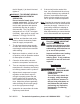
PARTS LIST Part 1 2 3 4 5 6 7 8 9 10 11 12 13 14 15 16 17 18 19 20 21 22 23 24 25 26 27 28 29 30 31 32 33 34 35 36 37 38 39 40 41 42 43 Description Air Nipple Oil Port Screw Lock Washer Cover O-Ring O-Ring Small piston Air Valve Seat O-Ring O-Ring Air Valve O-Ring Spring Air Cylinder Screw Lock Washer Sealing Ring Snap Retainer Sealing Ring O-Ring Air Piston Sealing Ring Piston Washer Spring Nut Sealing Ring Cylinder Screw Copper Washer Spring Ball Spring Ball Valve Base Foot Pedal Screw Lock Washer Washe
ASSEMBLY DIAGRAM SKU 98318 For technical questions, please call 1-800-444-3353.
90 day warranty Harbor Freight Tools Co. makes every effort to assure that its products meet high quality and durability standards, and warrants to the original purchaser that this product is free from defects in materials and workmanship for the period of 90 days from the date of purchase.