
Product manual


Page 6 For technical questions, please call 1-888-866-5797. Item 60653
SAFETY OPERATION MAINTENANCESPECIFICATIONS
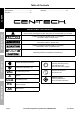
Specifications
Input 120VAC, 60Hz, 2A
Output 12 VDC - 10* A
12 VDC - 2* A
12 VDC Engine Start - 50 A
3125044
*Amperage is only present when the unit is connected to a battery or in START mode.
Operation Instructions
Read the ENTIRE IMPORTANT SAFETY INFORMATION section at the beginning of this
manual including all text under subheadings therein before set up or use of this product.
TO PREVENT SERIOUS INJURY:
DO NOT PLUG IN CHARGER UNTIL DIRECTED TO DO SO.
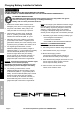
Controls
Wrong
Connection
Setting
switch
Type
switch
Charge
Meter
Charge
Status
Figure A: Controls
Wrong Connection:
This indicates that the cables are connected improperly.
Immediately disconnect the cables and connect
them properly to prevent damage to the battery.
Charge Status:
This will light up red when the power is connected.
This will light up green when the battery is fully charged.
This is disabled in start mode.
Setting switch:
Use this to switch between charging and start modes
and change the output amperage.
Battery Type switch:
Use this to set the battery type:
• Set to Regular for flooded and maintenance-free batteries.
• Set to AGM for Absorbed Glass Mat batteries.
WARNING! TO PREVENT EXPLOSION:
DO NOT USE WITH GEL BATTERIES.
Charge Meter (10 amp charge mode only):
100 75 50 25 0
CHARGE LEVEL %
Figure B: DISCHARGED BATTERY
Initial charge current to the battery is at maximum.
100 75 50 25 0
CHARGE LEVEL %
FIGURE C: BATTERY ALMOST FULLY CHARGED
Charge current to the battery is reduced.
100 75 50 25 0
CHARGE LEVEL %
Figure D: FULLY CHARGED BATTERY
Charge current to the battery is minimal
and the green LED is on.