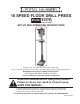
6 SPEED FLOOR DRILL PRESS Model 43378 Set up And Operating Instructions Diagrams within this manual may not be drawn proportionally. Due to continuing improvements, actual product may differ slightly from the product described herein. Distributed exclusively by Harbor Freight Tools®. 3491 Mission Oaks Blvd., Camarillo, CA 93011 Visit our website at: http://www.harborfreight.com Read this material before using this product. Failure to do so can result in serious injury. Save this manual.
Specifications Motor 120 VAC, 60 Hz, 3/4 HP, 1750 RPM; 5.
do the work of a larger industrial tool. There are certain applications for which this tool was designed. Do not modify this tool and do not use this tool for a purpose for which it was not intended. 7. Dress properly. Do not wear loose clothing or jewelry as they can be caught in moving parts. Protective, electrically non-conductive clothes and non-skid footwear are recommended when working. Wear restrictive hair covering to contain long hair. 8. Use eye and ear protection.
19. Do not operate tool if under the influence of alcohol or drugs. Read warning labels on prescriptions to determine if your judgment or reflexes are impaired while taking drugs. If there is any doubt, do not operate the tool. 20. Use proper size and type extension cord. If an extension cord is required, it must be of the proper size and type to supply the correct current to the tool without heating up. Otherwise, the extension cord could melt and catch fire, or cause electrical damage to the tool.
Vibration Hazard This tool vibrates during use. Repeated or long-term exposure to vibration may cause temporary or permanent physical injury, particularly to the hands, arms and shoulders. To reduce the risk of vibration-related injury: 1. Anyone using vibrating tools regularly or for an extended period should first be examined by a doctor and then have regular medical check-ups to ensure medical problems are not being caused or worsened from use.
5. Never place hands and arms near the workpiece to avoid the possibility of the work piece coming loose and striking you. 6. Before drilling, turn on the motor and check for bit wobble or machine vibration. If this is found, correct the problem before drilling. 7. Set the proper spindle speed for the specific drilling operation. 8. When finished with the Drill Press, always press the Switch to the OFF position, and remove the Lock Key. 9.
Assembly Assembly hardware is located in separate bags. Each bag contains the necessary parts for each assembly step. Remove all packing and protective material from the Drill Press components. 1. Position the Base (B6) on a level floor. It is recommended to bolt the Base to the floor using appropriate hardware (not supplied). Column Support (B4) Hex Screws (B5) Arm Locking Handle (B16) Table Crank (B8) 2. Place the Column Support (B4) on the Base, aligning the mounting holes. 3.
. Using two people, lift the Head Assembly up and onto the Column (B1). It should slide down on the Column Tube as far as it will go. Align it so that it faces straight forward, inline with the Base. 9. Screw in two Set Screws (21), into each side of the Head (1) and tighten with the Allen wrench. Head Assembly Hex Screw (17) Washer (15) Belt Tension Lock Knob (18) Hex Nut (14) Motor (13) Belt Tension Lever (19) Head Lock Set Screws (21) 10.
- Push the Motor up until the top of the pulleys align. Hold Motor in place. - Using a wrench, tighten four Hex Nuts (14) supporting the Motor. - Turn the Belt Tension Lever (19) counterclockwise to release belt tension. 13. Install V-belts (A1). Refer to the photos on page 7. - Turn the Belt Tension Lever (19) and move the pulleys closer together. - Place the Idler Pulley (A19) on the Idler Pivot (A20), and into the Pulley Cover center hole (See the Pulley Assembly Drawing at the end of this manual).
Operation Warning: Avoid personal injuries. Before operating this machine, review all Safety Warnings and Precautions listed on pages 2 through 5. 1. Loosen the Arm Locking Handle (B16) and turn the Table Crank (B8) to adjust the Table height to accommodate the workpiece being drilled. 2. Open the Chuck and insert the drill bit in the center. Tighten with the Chuck Key (A16). 3. Secure the workpiece (and backup material) to the Table using a vise and/or clamp. The workpiece sits on the backup material.
2. Mark the desired hole depth on the side of the workpiece. 3. Loosen the Depth Locking Screw Lock. 4. Turn the Feed Handle counterclockwise to bring the tip of the drill bit down, next to the hole depth mark. 5. Turn the Depth Stop Collar counterclockwise until it stops moving. 6. Tighten the Depth Locking Screw. 7. Turn the Drill Press ON and turn the Feed Handle counterclockwise until it drills the hole and stops at the set depth. 8. Turn the Drill Press OFF.
Maintenance Warning: Before performing any maintenance to this machine, remove the line cord from the electrical outlet. Removing the Chuck and Arbor During this procedure, refer to the Pulley and Spindle Assembly Drawing. 1. Adjust the Depth Stop Collar to hold the Chuck at a depth of three inches. 2. Align the key holes in the Spindle Shaft (A13) and the Quill (A11) by turning the Chuck by hand. 3. Insert the Wedge Drift Key (A17) into the key holes. 4.
6. With the screwdriver still in place, loosen the (inner) Hex Nut (38) until the Quill Spring Cap notch disengages from the Spring Seat (42) -- about 1/8 inch. Quill Spring Cap (39) Hex Nut (38) - Inner Quill Spring Cap Notches Hex Nut (38) - Outer 7. Turn the screwdriver counterclockwise and engage the next Spring Cap notch. Leave the screwdriver in place. 8. Tighten the (inner) Hex Nut just enough to engage the notch.
Troubleshooting SYMPTOM POSSIBLE CAUSE SOLUTION Drill bit burns or smokes - Incorrect spindle speed - Dull drill bit - Drilling too slowly - Lacking lubrication - Change spindle speed - Replace with new bit - Drill faster - Lubricate cutting area Makes unusual noise - Belt tension set wrong - Spindle dry - Loose spindle pulley - Loose motor pulley - Adjust belt tension - Lubricate spindle - Check pulley nut - Tighten Set screws Drill bit wobbles - Bent bit - Worn Spindle Bearings - Drill bit not i
Head Assembly Parts List Item # Description Item # Description 1 Head w/pointer and trim 24 Feed Handle 2 Cable Clamp 25 Spindle Feed Shaft 3 Pan Head Screw, M5x12 26 Collar Depth Stop, w/Scale 4 Hex Screw, M8x16 27 Stop Pin 5 Adjusting Lever 28 Connector Wire 6 Motor Support Bracket 29 Lock Washer, Ext., 5mm 7 Motor Support Bracket 30 Pan Head Screw, M5x12 8 Motor Mount 31 Switch 9 Lock Washer, o12 33 Switch Plate Cover 10 Hex Nut, M12x1.75 34 Pan Head Screw, ST4.
Head Assembly Drawing 41 SKU 43378 42 Page 16
Pulley and Spindle Assembly Parts List Item # Description A1 V Belt, M24 A2 Pulley Nut A3 Spindle Pulley A4 Pulley Insert A5 Ball Bearing A6 Spacer A7 Retaining Ring, 17 mm A8 Retaining Ring, 11 mm A9 Ball Bearing A10 Quill Gasket A11 Quill A12 Ball Bearing A13 Spindle Shaft A14 Arbor A15 Chuck A16 Chuck Key A17 Wedge Drift Key A18 Ball Bearing A19 Idler Pulley A20 Idler Pivot A21 Knob A22 Pan Head Screw, M5x8 A23 Pulley Cover A24 Washer, HD Screw, M16x12 A2
Pulley and Spindle Assembly Drawing When ordering a part from this drawing, add an “A” prefix to the part number.
Base and Table Assembly Parts List Item # Description B1 Column B2 Rack B3 Set Screw, Hex.
Base and Table Assembly Drawing When ordering a part from this drawing, add a “B” prefix to the part number.