Table of contents SAFETy Safety .................................................2 Specifications .....................................8 Setup ..................................................8 Operation ...........................................10 Maintenance ......................................12 Parts List and Diagram ......................14 Warranty ............................................16 SETUP WARNING SyMBOLS AND DEFINITIONS This is the safety alert symbol.
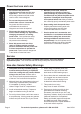
1. Power tool plugs must match the outlet. Never modify the plug in any way. Do not use any adapter plugs with grounded power tools. Unmodified plugs and matching outlets will reduce risk of electric shock. 4. Do not abuse the cord. Never use the cord for carrying, pulling or unplugging the power tool. Keep cord away from heat, oil, sharp edges or moving parts. Damaged or entangled cords increase the risk of electric shock. 2. Avoid body contact with grounded 5.
Power tool use and care SAFETy 1. Do not force the power tool. Use the correct power tool for your application. The correct power tool will do the job better and safer at the rate for which it was designed. 2. Do not use the power tool if the switch does not turn it on and off. Any power tool that cannot be controlled with the switch is dangerous and must be repaired. SETUP 3. Disconnect the plug from the power source before making any adjustments, changing accessories, or storing power tools.
10. WARNING: Some dust created by power sanding, sawing, grinding, drilling, and other construction activities, contains chemicals known [to the State of California] to cause cancer, birth defects or other reproductive harm.
Grounding SAFETy TO PREVENT ELEcTRIc SHOcK AND DEATH FROM INcORREcT GROUNDING WIRE cONNEcTION: check with a qualified electrician if you are in doubt as to whether the outlet is properly grounded. Do not modify the power cord plug provided with the tool. Never remove the grounding prong from the plug. Do not use the tool if the power cord or plug is damaged. If damaged, have it repaired by a service facility before use.
Extension cords 6. If you are using an extension cord outdoors, make sure it is marked with the suffix “W-A” (“W” in Canada) to indicate it is acceptable for outdoor use. SAFETy 0 – 2.0 18 18 18 18 16 2.1 – 3.4 18 18 18 16 14 3.5 – 5.0 18 18 16 14 12 5.1 – 7.0 18 16 14 12 12 7.1 – 12.0 18 14 12 10 12.1 – 16.0 14 12 10 16.1 – 20.0 12 10 * Based on limiting the line voltage drop to five volts at 150% of the rated amperes. SETUP 150´ (at full load) EXTENSION cORD LENGTH OPERATION 5.
Specifications Electrical Rating SAFETy 120VAC, 60Hz, 2A 13,000 OPM (Orbits No Load Speed per Minute) Dust Opening 13/8″ Backing Pad Dimensions 4″ W x 41/4″ L 4007520 SETUP Setup - Before Use: Read the ENTIRE IMPORTANT SAFETy INFORMATION section at the beginning of this manual including all text under subheadings therein before set up or use of this product.
Assembly SAFETy Note: The Sander’s dust collection system will only work if the sandpaper has holes that line up with the dust collection holes in the Backing Pad. (There are 4 other holes in the Backing Pad for the Screws). Snap the Dust Box into place over the dust port on the back of the sander. Functions Power cord OPERATION SETUP Power Switch Dust Box Item 61541 Sandpaper clamp For technical questions, please call 1-800-444-3353.
Operating Instructions SAFETy Read the ENTIRE IMPORTANT SAFETy INFORMATION section at the beginning of this manual including all text under subheadings therein before set up or use of this product. Tool Set Up TO PREVENT SERIOUS INJURy FROM AccIDENTAL OPERATION: Turn the Power Switch of the tool off and unplug the tool from its electrical outlet before adjusting the tool or installing accessories. Attaching Sandpaper to the Backing Pad SETUP 1.
1. Workpiece selection: a. Workpiece must be free of foreign objects. b. Wear a NIOSH-approved respirator and have appropriate ventilation whenever sanding pressure treated lumber. 2. Designate a work area that is clean and well-lit. The work area must not allow access by children or pets to prevent distraction and injury. 3. Route the Power Cord along a safe route to reach the work area without creating a tripping hazard or exposing the Power Cord to possible damage.
Maintenance and Servicing SAFETy Procedures not specifically explained in this manual must be performed only by a qualified technician. TO PREVENT SERIOUS INJURy FROM AccIDENTAL OPERATION: Turn the Power Switch of the tool off and unplug the tool from its electrical outlet before performing any inspection, maintenance, or cleaning procedures. TO PREVENT SERIOUS INJURy FROM TOOL FAILURE: Do not use damaged equipment. If abnormal noise or vibration occurs, have the problem corrected before further use.
Troubleshooting Tool operates slowly. Performance decreases over time. Excessive noise or rattling. Overheating. 2. No power at outlet. 2. Check power at outlet. If outlet is unpowered, turn off tool and check circuit breaker. If breaker is tripped, make sure circuit is right capacity for tool and circuit has no other loads. 3. Tool’s thermal reset breaker tripped (if equipped). 3. Turn off tool and allow to cool. Press reset button on tool. 4. Internal damage or wear.
PLEASE READ THE FOLLOWING cAREFULLy SAFETy THE MANUFACTURER AND/OR DISTRIBUTOR HAS PROVIDED THE PARTS LIST AND ASSEMBLY DIAGRAM IN THIS MANUAL AS A REFERENCE TOOL ONLY. NEITHER THE MANUFACTURER OR DISTRIBUTOR MAKES ANY REPRESENTATION OR WARRANTY OF ANY KIND TO THE BUYER THAT HE OR SHE IS QUALIFIED TO MAKE ANY REPAIRS TO THE PRODUCT, OR THAT HE OR SHE IS QUALIFIED TO REPLACE ANY PARTS OF THE PRODUCT.
MAINTENANcE OPERATION SETUP SAFETy Assembly Diagram Item 61541 For technical questions, please call 1-800-444-3353.
Limited 90 Day Warranty Harbor Freight Tools Co. makes every effort to assure that its products meet high quality and durability standards, and warrants to the original purchaser that this product is free from defects in materials and workmanship for the period of 90 days from the date of purchase.