Owner’s Manual & Safety Instructions Save This Manual Keep this manual for the safety warnings and precautions, assembly, operating, inspection, maintenance and cleaning procedures. Write the product’s serial number in the back of the manual near the assembly diagram (or month and year of purchase if product has no number). Keep this manual and the receipt in a safe and dry place for future reference. REV 15a Using an engine indoors CAN KILL YOU IN MINUTES. Engine exhaust contains carbon monoxide.
Table of Contents Specifications.............................................. 2 Safety ��������������������������������������������������������� 3 Setup........................................................... 7 Operationr��������������������������������������������������� 12 Maintenances���������������������������������������������� 17 Troubleshooting.......................................... 20 Parts Lists and Diagrams........................... 24 Warranties...........................................
WARNING SYMBOLS AND DEFINITIONS This is the safety alert symbol. It is used to alert you to potential personal injury hazards. Obey all safety messages that follow this symbol to avoid possible injury or death. Safety Indicates a hazardous situation which, if not avoided, will result in death or serious injury. Indicates a hazardous situation which, if not avoided, could result in death or serious injury. Indicates a hazardous situation which, if not avoided, could result in minor or moderate injury.
Set Up Precautions Safety 1. Gasoline fuel and fumes are flammable, and potentially explosive. Use proper fuel storage and handling procedures. Do not store fuel or other flammable materials nearby. 2. Have multiple ABC class fire extinguishers nearby. 3. Operation of this equipment may create sparks that can start fires around dry vegetation. A spark arrestor may be required. The operator should contact local fire agencies for laws or regulations relating to fire prevention requirements. 4.
19. Stay alert, watch what you are doing and use common sense when operating this piece of equipment. Do not use while tired or under the influence of drugs, alcohol or medication. 20. Do not overreach. Keep proper footing and balance at all times. This enables better control of the equipment in unexpected situations. 21. Use this equipment with both hands only. Using equipment with only one hand can easily result in loss of control. 22. Dress properly. Do not wear loose clothing or jewelry.
Service Precautions 1. Before service, maintenance, or cleaning: a. Turn the engine switch to its “OFF” position. Safety b. Allow the engine to completely cool. c. Then, remove the spark plug cap from the spark plug. 2. Keep all safety guards in place and in proper working order. Safety guards include muffler, air cleaner, mechanical guards, and heat shields, among other guards. 3. Do not alter or adjust any part of the equipment or its engine that is sealed by the manufacturer or distributor.
Set Up TO PREVENT SERIOUS INJURY: Operate only with proper spark arrestor installed. Operation of this equipment may create sparks that can start fires around dry vegetation. A spark arrestor may be required. The operator should contact local fire agencies for laws or regulations relating to fire prevention requirements. Safety Read the ENTIRE IMPORTANT SAFETY INFORMATION section at the beginning of this manual including all text under subheadings therein before set up or use of this product.
Assembly (continued) Safety 5. Connect the Pressure Hose (15) to the outlet fitting on the Pump (32) and firmly hand-tighten the nut. See Figure B. Figure B 6. Connect the Pressure Hose to the handle of the Spray Gun (2) and firmly handtighten the nut. See Figure C. Setup Figure C Wand 7. Remove the protective cap on the Wand (1) inlet. Insert the Wand into the Spray Gun tip and firmly hand-tighten the nut. See Figure D. Spray Gun Tip Figure D Operation Nozzle 8.
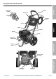
Spray Gun Handle Safety Components and Controls Handle Spray Gun Trigger Pressure Hose Trigger Lock Nozzles Setup Wand Frame Engine Pump Detergent Tank Lid Operation Detergent Tank Thermal Relief Valve ITEM 62214 Maintenance Pump Outlet Fitting Water Inlet Fitting For equipment technical questions, please call 1-888-866-5797.
Engine Controls Safety Air Filter Fuel Cap Setup Starter Handle Muffler Oil Drain Plug Operation Throttle Choke Fuel Valve Engine Switch Maintenance Oil Cap/Dipstick Page 10 For equipment technical questions, please call 1-888-866-5797.
High Altitude Operation Above 3000 feet NOTICE: Warranty void if necessary adjustments are not made for high altitude use. At high altitudes, the engine’s carburetor, governor (if so equipped), and any other parts that control the fuel-air ratio will need to be adjusted by a qualified mechanic to allow efficient high-altitude use and to prevent damage to the engine and any other devices used with this product. The fuel system on this engine may be influenced by operation at higher altitudes.
Operation Read the ENTIRE IMPORTANT SAFETY INFORMATION section at the beginning of this manual including all text under subheadings therein before set up or use of this product. Safety Pre-Start Checks Inspect engine and equipment looking for damaged, loose, and missing parts before set up and starting. If any problems are found, do not use equipment until fixed properly.
Starting the Engine a. Inspect the equipment and engine. b. Fill the engine with the proper amount and type of both unleaded gasoline and oil. c. TURN ON WATER SUPPLY, REMOVE NOZZLE, POINT WAND IN SAFE DIRECTION, AND HOLD DOWN TRIGGER UNTIL ALL AIR IS RELEASED FROM THE SYSTEM, AT LEAST 30 SECONDS. Then release the Trigger, lock it in the safety position and replace Nozzle before starting engine. Manual Start 1. To start a cold engine, move the Choke to the START position.
Starting the Engine (continued) Safety 5. Grip the Starter Handle of the Engine loosely and pull it slowly two times to allow the gasoline to flow into the Engine’s carburetor. Then pull the Starter Handle gently until resistance is felt. Allow Cable to retract fully and then pull it quickly. Repeat until the engine starts. 5 Note: Do not let the Starter Handle snap back against the engine. Hold it as it recoils so it doesn't hit the engine. 6. Allow the Engine to run for several seconds.
CAUTION Use the Pressure Washer only on surfaces able to withstand the force of the spray. 1. Choose the Nozzle that best meets the needs of the job. See Chart below. Only use the Nozzles on surfaces capable of withstanding the force of the spray. Only use the Black Nozzle when using pressure washer detergent. The power of the other Nozzles will propel mist back at the operator and can embed detergent into the surface.
Stopping the Engine and Pressure Washer 1. To stop the engine in an emergency, turn the Engine Switch off. Safety OFF 2. Under normal conditions, use the following procedure: O I a. Release the Trigger on the Spray Gun handle. b. Slide the Throttle or Speed Control Lever to SLOW (the “turtle”). c. Turn the Engine Switch off. d. Close the Fuel Valve. e. Turn the water supply off. 3. Squeeze the Trigger to release excess pressure. Setup 4.
Maintenance TO PREVENT SERIOUS INJURY FROM ACCIDENTAL STARTING: Turn the Power Switch of the equipment to its “OFF” position, wait for the engine to cool, and disconnect the spark plug cap before performing any inspection, maintenance, or cleaning procedures. TO PREVENT SERIOUS INJURY FROM EQUIPMENT FAILURE: Do not use damaged equipment. If abnormal noise, vibration, or excess smoking occurs, have the problem corrected before further use. Safety WARNING Follow all service instructions in this manual.
Safety Checking and Filling Fuel Engine Oil Change WARNING! TO PREVENT SERIOUS INJURY FROM FIRE: Fill the fuel tank in a well-ventilated area away from ignition sources. If the engine is hot from use, shut the engine off and wait for it to cool before adding fuel. Do not smoke. CAUTION! Oil is very hot during operation and can cause burns. Wait for engine to cool before changing oil. 1. Clean the Fuel Cap and the area around it. 2. Unscrew and remove the Fuel Cap. 3.
Spark Plug Maintenance Air Filter Maintenance 1. Remove the Air Cleaner Cover and the air filter(s) and check for dirt. Clean as described below. Spark Plug Cap 1. Disconnect spark plug cap from end of plug. Clean out debris from around spark plug. 2. Using a spark plug wrench, remove the spark plug. 3. Inspect the spark plug: If the electrode is oily, clean it using a clean, dry rag. If the electrode has deposits on it, polish it using emery paper.
Long-Term Storage When the equipment is to remain idle for longer than 20 days, prepare the Engine for storage as follows: Safety 1. CLEANING: Wait for Engine to cool, then clean Engine with dry cloth. NOTICE: Do not clean using water. The water will gradually enter the Engine and cause rust damage. Apply a thin coat of rust preventive oil to all metal parts. 2. FUEL: To protect the fuel tank during storage, fill the tank with gasoline that has been treated with a fuel stabilizer additive.
Troubleshooting FUEL RELATED: FUEL RELATED: 1. No fuel in tank or fuel valve closed. 1. Fill fuel tank with fresh 87+ octane unleaded stabilizer-treated gasoline and open fuel valve. Do not use gasoline with more than 10% ethanol (E15, E20, E85, etc.). 2. Choke not in START position, cold engine. 2. Move Choke to START position. 3. Gasoline with more than 10% ethanol used. (E15, E20, E85, etc.) 3. Clean out ethanol rich gasoline from fuel system. Replace components damaged by ethanol.
Problem Engine misfires Possible Causes Probable Solutions 1. Check wire connections. 2. Incorrect spark plug gap or damaged spark plug. 2. Re-gap or replace spark plug. 3. Defective spark plug cap. 3. Replace spark plug cap. 4. Old or low quality gasoline. 4. Use only fresh 87+ octane stabilizer-treated unleaded gasoline. Do not use gasoline with more than 10% ethanol (E15, E20, E85, etc.). 5. Incorrect compression. 5. Diagnose and repair compression.
Possible Causes Probable Solutions 1. Push firmly into injector. 2. Tube cracked or split. 2. Replace tube. 3. Wrong Nozzle. 3. Switch to Black Nozzle. 4. Injector turned off. 4. Turn collar counterclockwise. 5. Injection tube strainer clogged. 5. Clean strainer. 6. Nozzle blocked. 6. Clean Nozzle. 7. Dried detergent in injector. 7. Dissolve by running warm water through the injection tube. Run clean water through injector until clear. Safety Problem No intake of detergent 1.
Parts Lists and Diagrams General Parts List Safety Part Setup 1 2 3 4 5 6 7 8-1 8-2 8-3 8-4 8-5 9 10 11 12 13 14 15 Description Wand Spray Gun Spray Gun Holder Knob Handle Handle Grip Hose Hanger Red Nozzle – 0° Yellow Nozzle – 15° Green Nozzle – 25° White Nozzle – 40° Black Nozzle – Detergent Nozzle Grommet Bolt Nozzle Panel Handle Knob Frame Wand Holder Pressure Hose Qty.
Safety General Assembly Diagram - - - - Maintenance Operation Setup - ITEM 62214 For equipment technical questions, please call 1-888-866-5797.
Pump Parts List Part Safety Setup 1A 2A 6A 7A 8A 9A 10A 11A 12A 13A 14A 15A 16A 17A 18A 19A 20A 21A 22A 23A 24A 25A 26A 27A 28A 29A 30A Description Head Bolt M8 x 45 Pump Head Plug O-Ring Ø7.66 x 1.78 Plug - Aluminum O-Ring Ø14 x 1.7 Check Valve O-Ring Ø9 x 1 Seat By-Pass Jet O-Ring Ø10.82 x 1.78 Piston Guide Ring O-Ring Ø6.07 x 1.78 O-Ring Ø6.02 x 2.62 Piston Nut M6 Grub Screw M6 x 16 Handle Insert Plate Spring Spring Gasket O-Ring Ø23.52 x 1.78 Bushing Bushing Oil Seal Housing Qty.
ITEM 62214 1 2 7 6 For equipment technical questions, please call 1-888-866-5797.
Engine Parts List Part Safety Setup Operation Maintenance 1B 2B 3B 4B 5B 6B 7B 8B 9B 10B 11B 12B 13B 14B 15B 16B 17B 18B 19B 20B 21B 22B 23B 24B 25B 26B 27B 28B 29B 30B 31B 32B 33B 34B 35B 36B 37B 38B 39B 40B 41B 42B 43B 44B 45B 46B 47B 48B 49B 50B 51B 52B 53B 54B 55B 56B 57B Description Cylinder Head Gasket Cylinder Head Cover Subassembly Cylinder Head Cover Gasket Breather Tube Bolt Stud Stud Stud Pin Cylinder Head Bolt Spark Plug Cylinder Head Subassembly Crankcase Subassembly.
Maintenance Operation Setup Safety Engine Assembly Diagram ITEM 62214 For equipment technical questions, please call 1-888-866-5797.
Warranties Safety Limited 90 Day Warranty Harbor Freight Tools Co. makes every effort to assure that its products meet high quality and durability standards, and warrants to the original purchaser that this product is free from defects in materials and workmanship for the period of 90 days from the date of purchase.
Emissions Control System Warranty Where a warrantable condition exists, HFT will repair your engine at no cost to you including diagnosis, parts and labor. Manufacturer’s Warranty Coverage The 2014-2015 engines are warranted for two (2) years. If any emissions-related part on your engine is defective, the part will be repaired or replaced by HFT.
3491 Mission Oaks Blvd.