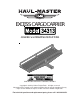
EXCESS CARGO CARRIER ASSEMBLY and OPERATING INSTRUCTIONS ® 3491 Mission Oaks Blvd. / Camarillo, CA 93011 Copyright © 1997 by Harbor Freight Tools®. All rights reserved. No portion of this manual or any artwork contained herein may be reproduced in any shape or form without the express written consent of Harbor Freight Tools. For technical questions and replacement parts, please call 1-800-444-3353.
® SPECIFICATIONS Platform Dimensions Carrying Capacity Hitch Size Total Weight 20" x 60" 500 lbs. 2" Standard 52 lbs. SAVE THIS MANUAL You will need the manual for the safety warnings and cautions, assembly instructions, operating procedures, maintenance procedures, trouble shooting, parts list, and diagram. Keep your invoice with this manual. Write the invoice number on the inside of the front cover. Keep both this manual and your invoice in a safe, dry place for future reference.
® times. Wear a full face shield if you are producing metal filings or wood chips. Wear an ANSI approved dust mask or respirator when working around metal, wood, and chemical dusts and mists. 9. DO NOT ABUSE THE POWER CORD. Do not yank it to disconnect it from the receptacle. Do not carry tools by the cord. 10. DO NOT OVERREACH. Keep proper footing and balance at all times. Do not reach over or across running machines. 11. MAINTAIN TOOLS WITH CARE.
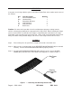
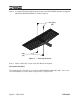
UNPACKING If any parts are missing or broken, please call Harbor Freight Tools at the number on the cover of this manual. Ref A N/A B C1 C2 D Item Description Receiver Mounting Bar Hardware Bag Detachable Side Rail Side Rail Brace Side Rail Brace Bed Frame Quantity 1 1 2 3 3 1 Caution: Be aware of the possible risk of fire and damage to property resulting from the vehicle’s exhaust pipe pointing at the cargo put in this Cargo Carrier.
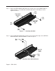
® Step 4: Insert two HEX BOLTS (#E) through the top of the BED FRAME and down through the RECEIVER MOUNTING BAR as shown in Figure 2. Hex Bolts (#E) Nuts (#F) Figure 2 — Inserting Hex Bolts Step 5: Attach a NUT (#F) to each of the HEX BOLTS and tighten. Detachable Side Rails The following Steps show how to assemble the DETACHABLE SIDE RAILS (#B). These side rails should always be in place when using the Excess Cargo Carrier.
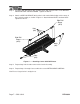
Step 1: Attach one DETACHABLE SIDE RAIL to the outside corners of the BED FRAME as shown in Figure 3. Assemble with one BOLT (#G) and one NUT (#H) per corner. Tighten the NUTS. Bolt (#G) Detachable Side Rail (#B) Nut (#H) Detachable Side Rail (#B) Bolt (#G) Nut (#H) Figure 3 — Attaching Side Rails Step 2: Place a SIDE RAIL BRACE (#C1) outside on the vertical folded edges of the DETACHABLE SIDE RAIL and BED FRAME as shown in Figure 4.
® Step 3: Assemble with two BOLTS (#G) and two NUTS (#H) using the holes in the DETACHABLE SIDE RAIL and BED FRAME. Tighten the NUTS. Step 4: Attach a SIDE RAIL BRACE (#C2) to the inside vertical folded edges of the corner of the Carrier Assembly as shown in Figure 5. Attach with two BOLTS and two NUTS. Tighten the NUTS.
OPERATION Step 1: Request a friend’s help to lift the Excess Cargo Carrier. Step 2: Lift the Excess Cargo Carrier and place the RECEIVER MOUNTING BAR into the Hitch Receiver mounted to your vehicle. Step 3: Line up the horizontal hole in the RECEIVER MOUNTING BAR with the hole in your Hitch. When the holes line up, place your locking mechanism through the holes to secure the Excess Cargo Carrier. Your Excess Cargo Carrier can be loaded with up to 500 lbs. of cargo.
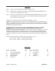
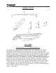
® ASSEMBLY DIAGRAM DISCLAIMER PLEASE READ THE FOLLOWING CAREFULLY THE MANUFACTURER AND/OR DISTRIBUTOR HAS PROVIDED THE PARTS DIAGRAM IN THIS MANUAL AS A REFERENCE TOOL ONLY. NEITHER THE MANUFACTURER NOR DISTRIBUTOR MAKES ANY REPRESENTATION OR WARRANTY OF ANY KIND TO THE BUYER THAT HE OR SHE IS QUALIFIED TO MAKE ANY REPAIRS TO THE PRODUCT OR THAT HE OR SHE IS QUALIFIED TO REPLACE ANY PARTS OF THE PRODUCT.