5-Speed Drill Press Model 38119 Set up And Operating Instructions Distributed exclusively by Harbor Freight Tools®. 3491 Mission Oaks Blvd., Camarillo, CA 93011 Visit our website at: http://www.harborfreight.com Read this material before using this product. Failure to do so can result in serious injury. Save this manual. Copyright© 1998 by Harbor Freight Tools®. All rights reserved.
THANK YOU for choosing a Harbor Freight Tools product! For future reference, please complete the owner’s record below: Model: _________________ Serial No: __________________________ Purchase Date: ______________ SAVE THE RECEIPT, WARRANTY CARD AND THESE INSTRUCTIONS. It is important that you read the entire manual to become familiar with the unit BEFORE you begin assembly.
Unpacking Unpack and check contents. Make sure you have all parts described in the Parts Lists and Figure 1 on page 3. Remove all preservative lubricants from parts with a clean dry cloth. Some of the parts are heavy and may require two people for lifting. If any parts are missing or broken, please call Harbor Freight Tools at 1-800-444-3353. The shipping box should contain: A. C. E. G. Table Assembly Instruction manual and warranty card Head assembly One (1) bag of loose items B.
Know Your Drill Press 1. Pulley Cover 2. Belt Tension Locking Screw 3. Head Lock Set Screws 4. Table Support 5. Column Support 6. Table Support Locking Handle 7. Base 8. Quill Spring Assembly 9. Pointer 19. Switch 10. 11. 12. 13. 14. 15. 16. 17. 18. 20.
. Clean and uncluttered The Operator COMMON SENSE and CAUTION are factors which cannot be built into any product. These factors must be supplied by the operator. Please remember: 1. Prevent body contact with grounded surfaces such as pipes or radiators. 2. Stay alert. Never operate equipment if you are tired. 3. Do not operate the product if under the influence of alcohol or drugs. Read warning labels on prescriptions to determine if your judgment/reflexes might be impaired. 4.
Operation 1. This drill press is designed for use with DRILL BITS and MORTISING ATTACHMENTS only. The use of other cutting tools or accessories could be hazardous. 2. Always use clamps, or a drill vise bolted to the table, to hold the work. It should never be held in place by just your hand. 3. Never force the tool or attachment to do the work of a larger industrial tool. It is designed to do the job better and more safely at the rate for which it was intended. 4. Always unplug the cord by the plug.
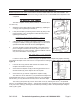
2. Slide the Table Support with Table over the Column (#11) and secure at a convenient position by tightening the Table Support Locking Handle. Head to Column 1. It may be necessary to unscrew the Head Lock Set Screws (#3) slightly to ensure they do not protrude internally, as this will prevent the head from sliding fully into position. 2. With assistance, raise the Head and place it on top of the Column, ensuring it slides home fully. 3.
Settings and Adjustments Before adjustments are made, ensure that the machine is SWITCHED OFF AND UNPLUGGED. Also make sure all locking handles and securing screws are FULLY TIGHTENED when adjustments are completed. TO ADJUST THE TABLE Figure 3 The table is capable of being raised, lowered, or swiveled about the column by: 1. Slackening off the table support locking handle (A), adjusting accordingly, and re-tightening the handle; or, 2.
CHANGING DRILL (SPINDLE) SPEED Before changing the speeds, make sure the machine is switched OFF and UNPLUGGED. 1. Open the pulley cover. 2. Slacken off the Belt Tension Locking Screw to relieve any tension on the drive belt. 3. Consult the chart inside the pulley cover (or Figure 5 on page 10) and position the belt on the pulleys according to the spindle/drill speed required 4.
clamped. Any tilting, twisting or shifting will result not only in a roughly drilled hole but also increases the chances of damage to the drill. 5. FOR FLAT WORK, lay the piece on to a wooden base and clamp it down firmly against the table to prevent it from turning. 6. FOR SMALL MATERIALS that cannot be clamped to the table, use a drill press vice. Make sure the vice is clamped or bolted to the table. 7.
Grounding/Voltage Warning Common household current is 110-120 volts. As long as your tool is rated from 110-120V there will be no complications using this tool with household receptacles. Plug the press into a 110-120V properly grounded outlet protected by a 15-amp, dual element time delay or circuit breaker. NEVER try to plug a 110-120V tool into a 220-240V circuit (or vice versa) or serious complications and possible injury to the operator may occur. The plugs have different shapes to prevent this.
Maintenance CLEANING: Regularly clean the work surface with dry brush or clean cloth. Keep machined parts of the press lightly greased. Always keep the motor and chuck clean. Prevent metal, wood, dust and debris from accumulating in this area. If jaws do not operate smoothly, have the chuck serviced by a qualified technician. LUBRICATION: For average use, lubricate twice a year with #20-30 weight household oil. Lubricate more frequently with increased usage.
Parts List - Pulley Assembly (Figure 7) Item 1 2 3 4 5 6 7 8 9 10 11 12 13 14 15 16 Description Rubber Bushing Knob Pan Head Screw “V” Belt K26 Pulley Cover w/labels Washer Hd. Screw M6 Retaining Ring 17mm Ball Bearing 60203 Spacer Pulley Insert Retaining Ring 22mm Spindle Pulley Hex Socket Set Screw Pan Head Screw M5 Cable Clamp Foam Washer No. 2005010 1505008 GB818-85 0805007 0805000 GB9074.1-88 GB894.1-86 GB278-89C 1302023 0802022A GB894.
Parts Diagram - Head Assembly (Figure 8) Part Numbers shown below have an “A” suffix Item 1A 2A 3A 4A 5A 6A 7A 8A 9A 10A 11A 12A 13A 14A 15A 16A 17A Description Head w/Roll Pin/trim Locknut M8 Washer 5/16 Hex. Screw M8 Motor Pulley Screw Hex. Skt. M6 Motor Stop Motor Spring (Motor Stop) Belt Tension Lock Screw Hex. Skt. Screw M8 Knob Feed Handle Pinion Shaft Hex. Nut M8 Fit Set Screw M8 Ext. Lockwasher 5mm SKU 38119 No. 0802001 DIN985-85 GB97.
Quill Assembly (Figure 9) Base and Table (Figure 10) 11 10 8 Part Numbers shown here have “B” suffix Part Numbers shown here have “C” suffix 9 Item 1B 2B 3B 4B 5B 6B 7B 8B 9B 10B 11B 12B Description Quill Gasket Ball Bearing Quill Shaft Spindle Shaft Stop Rod Hex. Nut M4 Pan Hd. Screw M5x20 Hex. Nut M6 Chuck Collar Retaining Ring Chuck Key No. 1303003 GB278-89 0803002A 0803001B 0803005 GB6170-86 GB818-85 GB6170-86 1303009 0803004 GB894.
LIMITED 90 DAY WARRANTY Harbor Freight Tools Co. makes every effort to assure that its products meet high quality and durability standards, and warrants to the original purchaser that this product is free from defects in materials and workmanship for the period of 90 days from the date of purchase.