38144 16-Speed Drill Press Assembly and Operating Instructions ® 3491 Mission Oaks Blvd., Camarillo, CA 93011 Visit our Web site at http//www.harborfreight.com Copyright 1998 by Harbor Freight Tools®. All rights reserved. No portion of this manual or any artwork contained herein may be reproduced in any shape or form without the express written consent of Harbor Freight Tools. For technical questions, please call 1-800-444-3353.
THANK YOU for choosing a Harbor Freights Tool product! For future reference, please complete the owner’s record below: Model: _________________ Serial No: __________________________ Purchase Date: ______________ SAVE THE RECEIPT, WARRANTY CARD AND THESE INSTRUCTIONS. It is important that you read the entire manual to become familiar with the unit BEFORE you begin assembly.
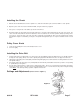
Figure 1 Spindle Belt is M24 Figure 2 #38144 Motor Belt is M25 REV 10/03 Page 3
Work Area TO AVOID RISK OF PERSONAL INJURY, EQUIPMENT DAMAGE, FIRE AND SHOCK, MAKE SURE YOUR WORK AREA IS: Free of damp, wet or rainy conditions Free of flammable gasses or liquids Childproof - use padlocks, master switches and remove starter keys when not in use. Well-lit Clean and uncluttered Well-ventilated The Operator COMMON SENSE AND CAUTION ARE FACTORS WHICH CANNOT BE BUILT INTO ANY PRODUCT. THESE FACTORS MUST BE SUPPLIED BY THE OPERATOR.
Before Operating √ Know the machine. potential hazards. Learn its applications and limitations, as well as the specific √ Check for damage. If part of the machine inspected to ensure that it can perform its in doubt, the part should be replaced. √ is damaged, it should be carefully intended function correctly. If Be sure the switch is OFF before plugging in. √ Before starting machine check to ensure that all chuck keys, spanners and wrenches are removed from the machine.
Assembly (Please refer to Figure 2 and Parts Lists/Diagrams) CAUTION! Consider the weight of the components and take necessary precautions when lifting components. Assistance will be required when assembling. Before adjustments are made, ensure that the machine is SWITCHED OFF AND UNPLUGGED. Also make sure all locking handles and securing screws are FULLY TIGHTENED when adjustments are completed.
Installing the Chuck 1. With the Chuck Guard lifted clear of the spindle nose, slide the work table up the column to within 6” of the spindle. 2. Open the jaws of the chuck to their maximum width, using the Chuck Key supplied. 3. Put a piece of scrap wood on the table to protect the Chuck Nose. 4. Ensuring all parts are thoroughly clean and dry and burr free, insert the arbor (#14) firmly into the end of the chuck.
Before adjustments are made, ensure that the machine is SWITCHED OFF AND UNPLUGGED. Also make sure all locking handles and securing screws are FULLY TIGHTENED when adjustments are completed. TO ADJUST THE TABLE The table is capable of moving in four directions (see Figure 3). 1. Raise or lower the table by slackening off the arm locking handle (A) and turning the crank (C) CLOCKWISE TO RAISE and COUNTER CLOCKWISE TO LOWER. 2. Swivel the table about the column by slackening off the arm locking handle.
3. Consult the chart inside the pulley cover (or Figure 5) and position the belts on the pulleys according to the spindle/drill speed required 4. When the belts have been correctly positioned, tighten them by turning the Belt Tension Lever counter clockwise until the belt deflects by approximately 1/2’ at its center when using reasonable thumb pressure. Lock the lever in this position with the two Locking Knobs. Operation 1.
Drill Speed Table Note: Spindle Belt M24, Motor Belt M25 The table below shows the belt arrangements for given drill speeds (a full chart is also located on the inside of the pulley cover). After Operation 1. Remove all residue from the machine and thoroughly clean all surfaces. 2. Make sure all components are dry and machined surfaces lightly oiled. 3. Remove drill bits and store in a safe place. 4. Child-proof the machine and work area.
Extension Cords Your tool has a three-prong plug, therefore you must use a three-prong extension cord. Only use rounded jacket extension cords listed by the Underwriters Laboratories (UL). The extension cord must have a minimum wire size depending on the amperage of the tool and the length of the extension cord. This size is determined by its AWG (American Wire Gauge) rating. The smaller the gauge, the greater the cable’s capacity.
#38144 Page 12
Figure 7 - Parts List - Pulley and Spindle Assembly 1b 1a Item 1a 1b 2 3 4 5 6 7 8 9 10 11 12 13 14 Description No. “V” Belt M24 1505010 “V” Belt M25 Pulley Nut 1302025 Spindle Pulley 1305009A Pulley Insert 1302022 Ball Bearing17mm 60203 GB2778-89C Spacer 1302023 Retaining Ring 17mm GB894.1-86B Retaining Ring 11mm GB894.1-86A Ball Bearing 60201 GB278-89A Quill Gasket 1303003 Quill 1303002B Ball Bearing 80202 GB278-89D Spindle Shaft 13003001A Arbor 1503007 #38144 Item 15 Description Chuck No.
Figure 8 - Parts List - Head Assembly Part Numbers shown here have an “A” suffix Item 1A 2A 3A 4A 5A 6A 7A 8A 9A 10A 11A 12A 13A 14A 15A 16A 17A 18A 19A 20A 21A 22A 23A Description No. Head w/pointer and trim 1302001A Cable Clamp 15020114A Pan Head Screw M5 GB818-85B Hex. Screw M8 GB5781-86B Adjusting Lever 1502006 Motor Support Bracket 1502002 Motor Support Bracket 1502003 Motor Mount 1502007A Lockwasher 12mm GB93-87 Nut Hex. M12x1.75 GB6170-86E Motor Pulley 1505005 Skt.
Figure 9 - Parts List - Base and Table Part Numbers shown here have a “B” suffix Item 1B 2B 3B 4B 5B 6B 7B 8B 10B 11B 12B 13B 14B 15B 16B 17B 18B 19B #38144 Description Column Rack Hex. Socket Screw Set M10 Column Support Hex. Head Screw Base Table Support w/indicator Crank Gear Pin Skt. Screw Set M6 Bevel Table Lock Screw M16 Table Clamp Arm w/scale Table Arm Locking Handle Helical Gear Worm Collar No.