0” Auto Planer Model 41921 Assembly And Operation Instructions Due to continuing improvements, actual product may differ slightly from the product described herein. ® 3491 Mission Oaks Blvd., Camarillo, CA 93011 Visit our website at: http://www.harborfreight.com To prevent serious injury, read and understand all warnings and instructions before use. Copyright© 1999 by Harbor Freight Tools®. All rights reserved.
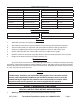
Specifications Motor 115 V/60 Hz. 2.2 HP Power Cord 5’9”, 3-pole, UL listed Amps 7.1 (no load) Overall Dimensions 22” x 16” x 23-1/4” Cuts per Minute 16,000 Weight 89.5 lb. Cutter Head RPM’s 8,000 (no load) Cutting Knives 2, Bi-Metal, M-2 edge Length of unbutted stock 8” minimum Feed Rate 23 feet per minute Width of stock 10” max. Table Dimension 12-5/8”L x 10-1/4”W Thickness of stock 1/4” - 5” Sound Level 94 dB Depth of cut 1/8” max.
. Keep work area clean. Cluttered areas invite injuries. 3. Observe work area conditions. Do not use tools in damp, wet, or poorly lit locations. Don’t expose to rain. Keep work area well lit. Do not use electrically powered equipment in the presence of flammable gases or liquids. 4. Keep children away. Children must never be allowed in the work area. Do not let them handle machines, tools, or equipment. 5. Store idle equipment.
Special Warnings when using this Planing Machine Using this Planer may create special hazards. Take particular care to safeguard yourself and those around you. 1. Electrical Safety. Never operate any tool if there is an electrical hazard. Never operate an electrical tool in wet conditions. Never operate a tool with an improper electrical cord or extension cord. Never operate an electrical tool unless it is plugged into a properly grounded outlet, which supplies 110-120 Volts at 60 Hz.
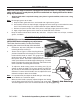
Installation 1. It is important that the machine be located on a solid, level platform. Find a location that has easy access to 110-120 Volt electrical service. Make sure this machine is located in a well lighted and well ventilated area. The floor should be resistant to vibration. There must be adequate room to insert and remove workpieces through the planer. . To permanently install the machine, check the platform to be sure it is even and level. Make any required corrections to the platform.
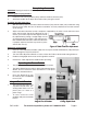
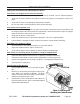
Completing Assembly WARNING: Unplug the machine before any assembly or adjustment. Attaching the Carrying Handles 1. Locate the two carrying handles (349), and their hardware, Screws (327). . Attach the handles to the top of the machine firmly using the screws. Installing the table extensions 1. With the roller up, place each table extension bracket (157) onto the table (125) and attach using two cap screws (164).
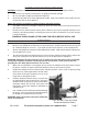
Safety Check Prior to Operation Warning: Unplug the machine and turn the power switch OFF before inspecting the machine. 1. Check to be sure all parts and fasteners are properly attached and tight. . Be sure the blade is properly installed and adjusted. 3. Check the operation of the Table Adjustment Handle (150). One rotation of the handle will raise or lower the table by 2mm (0.0787”). Plug in the machine to prepare to check the motor and blade function. 1.
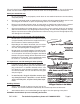
Suggestions for Better Planing This tool is ideal for finishing wood boards. You can use it to level or remove veneers. You can level warped boards. You can convert rough boards into finished wood. You can shape boards to a desired size. Select your wood with care. 1. Be sure your wood is dry and properly cured. Green or wet wood will continue to shrink and may warp after planing. . Do not use splintered wood, or wood which may splinter while being worked.
Maintenance When not in use, keep the machine unplugged and covered. Store it in a dry place. Store the safety switch cover in a safe place to prevent unauthorized use. Unplug the machine before doing any maintenance. 1. Regular lubrication is required to keep your planer in good condition, and assure a long service life. Note: Do not apply grease to the belts. a. Keep the table guide rods clean, and coated with a light coat of grease. b.
Troubleshooting Unplug the machine before attempting any repairs. If the Planer runs roughly or has excessive vibration: 1. Verify that Knife Blades are not chipped, are securely installed, and are adjusted properly. . Verify that all chains and belts are properly routed on their pulleys and sprockets, and are not loose. 3. Verify that the Table is not damaged, and operates smoothly. 4. Be sure the Crank is removed from the Planer before operation. If the Planer will not operate at all: 1.
#41921 10” Auto Planer Parts List, Main Unit Please refer to Parts Diagram on Page 12 Part 101 102 103 104 105 106 107 108 109 110 111 112 113 114 115 116 117 118 119 120 121 122 123 124 125 126 127 128 129 130 131 132 Description Washer, m6 Cap Screw, m6 x 12 Screw, m6 x 50 Washer, m6 Retaining Ring, m15 Shaft Sprocket Retaining Ring, m15 Shaft Pawl Bushing Washer, m6 Sprocket Cover Cap Screw, m6 x 16 Screw Bolt Frame Sprocket, m16 Sprocket Frame Sprocket Washer, m10 Nut, m10 Washer, m8 Nut, m8 Sprocket F
#41921 10” Auto Planer Parts Diagram, Main Unit Please refer to Parts List on Page 11 SKU 41921 For technical questions, please call 1-800-444-3353.
#41921 10” Auto Planer, Additional Parts List Please refer to Parts Diagrams on Page 14 and 15 Part Description Motor Assembly Q’ty Part Description Q’ty 317 Cutter Head 1 201 Motor Housing 1 318 Key, m5 x 5 x 20 1 202 Stator 1 319 Driven Pulley 1 203 Washer, m5 1 320 Knife Gauge 1 204 Fan Casing 1 321 Adjustable Bolt 4 205 Screw, m5 x 85 2 322 Non-Belt, J-750-6 1 206 Bearing, 6201ZZ 1 323 Nut, m16 x 1.
#41921 10” Auto Planer Parts Diagram, Motor Assembly Please refer to Parts List on Page 13 SKU 41921 For technical questions, please call 1-800-444-3353.
#41921 10” Auto Planer Parts Diagram, Cutter Assembly Please refer to Parts List on Page 13 SKU 41921 For technical questions, please call 1-800-444-3353.