Geared Head Drill / Mill Machine Model 42827 Assembly & Operating Instructions ® 3491 Mission Oaks Blvd., Camarillo, CA 93011 Visit our Web site at http://www.harborfreight.com TO PREVENT SERIOUS INJURY, READ AND UNDERSTAND ALL WARNINGS AND INSTRUCTIONS BEFORE USE. Copyright© 2005 by Harbor Freight Tools® . All rights reserved. No portion of this manual or any artwork contained herein may be reproduced in any shape or form without the express written consent of Harbor Freight Tools.
Motor: 6 Speeds (rpm): Motor rpm’s: Spindle Taper: Spindle Collar: Spindle Stroke: Spindle to Table: SPECIFICATIONS 110V/60Hz Single Phase Drill Cap: 1.5 HP, 15 Amps Face Mill Cap: 95-175-310-450-850-1500 End Mill Cap: 1720 Tapping Cap: R8 Max. Y-Travel: 1.
SAFETY WARNING & CAUTIONS READ ALL INSTRUCTIONS BEFORE USING THIS TOOL! 1. KEEP WORK AREA CLEAN. Cluttered areas invite injuries. 2. OBSERVE WORK AREA CONDITIONS. Do not use tools in damp, wet, or poorly lit locations. Don’t expose to rain. Keep work area well lit. Do not use electrically powered equipment in the presence of flammable gases or liquids. 3. KEEP CHILDREN AWAY. Children must never be allowed in the work area. Do not let them handle machines, tools, or equipment. 4. STORE IDLE EQUIPMENT.
14. STAY ALERT. Watch what you are doing. Do not operate this machine when you are tired. 15. DO NOT OPERATE THIS MACHINE WHILE UNDER THE INFLUENCE OF ALCOHOL, DRUGS, OR PRESCRIPTION MEDICINES. 16. CHECK FOR DAMAGED PARTS. Before using any tool, any part that appears damaged should be carefully checked to determine that it will operate properly and perform its intended function.
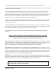
FEATURES AND CONTROLS OF THE #42827 DRILL / MILL MACHINE Figure 1. 1. 2. 3. 4. 5. 6. 7. 8. 9. 10. 11. Column Head Collar Head Collar Lock Bolt Head Crank Lock Nut Oil Drain Plug Table Feed Wheel Travel Stop Knob Red Bush Button Green Push Button Page 5 SKU # 42827 12. 13. 14. 15. 16. 17. 18. 19. 20. 21. 22.
UNPACKING AND INSTALLATION 1. 2. Remove protective crating and skids carefully. In the event of damage in transit, contact Harbor Freight Tools immediately. Read the owner’s manual and become familiar with the parts and controls on the drawings before using this machine, as familiarity with the controls will enhance your ability and safety in using it. INSTALLATION 1. 2. 3. 4. 5. It is important that the machine be located on a hard, solid, level floor.
BASIC OPERATION Prior to Operation 1. Check the oil level, and if necessary fill to the mid point of the oil level window. Basic Controls Please refer to Figure 1 on page 5. 1. Raise and lower the Head by using the Head Crank (#4). 2. Feed the Spindle using Spindle Feed Handle (#16). Precise movements may be made using the Spindle Micro Feed Handle (#15). 3. Move or feed the table from side to side by using the Table Feed Wheel (#7). 4. Move the Table front to back using the Cross Table Feed Wheel (#13).
Preparing for Milling 1. Adjust the positive stop gauge to its uppermost position. 2. Using the spindle feed handle, adjust the bit to approximately the correct height. Tighten the knob in the center of the spindle feed handle (#16). 3. Set the final vertical adjustment using the micro feed handle. 4. Lock the rack sleeve at this height with the fixed bolt. Preparing for Tapping 1. Adjust the positive depth gauge to the required position. 2. Loosen the knob in the center of the spindle feed handle.
Installing and Changing Tools WARNING: Be sure the power is turned off and the machine unplugged before installing or changing tool bits. Removing Face Mill or Drill Chuck Arbor 1. Remove the arbor bolt cover (#21) on the top of the head body (#20). 2. Loosen the arbor bolt at the top of the spindle shaft approximately 2 turns with a suitable wrench. 3. Rap the top of the arbor bolt with a mallet. 4.
Additional Safety Rules for Drilling and Milling 1. Be sure the drill bit or cutting tool is securely locked in the chuck. 2. Be sure the chuck key is removed from the chuck before turning on the power. 3. Adjust the table or depth stop to avoid drilling into the table. 4. Shut off the power, remove the drill bit or cutting tool, and clean the table before leaving the machine. 5. Always use clamps or a vise to hold the workpiece, to prevent it from moving, rotation or flying off while being machined. 6.
The Table Travel is not Balanced 1. The spindle taper gap is too wide. Adjust the arbor bolt properly. 2. One of the leaf bolts may be loose. Check and tighten them if necessary. 3. The feed is too deep. Reduce the depth of the cut, and make several passes to reach the required depth. 4. The gib strip may be out of adjustment. Check it and adjust it if necessary. There is a vibration,and the cut is not smooth 1. The spindle bearing may be improperly adjusted or is worn.
ELECTRICAL WIRING NOTE: This machine is designed to operate on 110 Volt/60 Hz Single Phase power supply only. This machine is supplied with a 3-prong grounded plug. Use only a power supply which is grounded, and which is protected by an appropriate circuit breaker. Check with a qualified electrician before using this machine. Serious injury or damage to property can result from improper electrical connection.
MAINTENANCE After each use: 1. Turn off the power switch and unplug the machine from its power source. 2. Remove any tool bits, clean and lubricate them, and return them to their storage case. 3. Using a stiff bristle brush, brush off all chips and shavings left from the machining operation. 4. Using a rag, wipe off any excess or dirty oil or cutting fluid left on the machine. 5. Lubricate the points indicated in Figure 2. Apply light grease or oil to all unpainted metal to prevent corrosion. 6.
GEARED HEAD DRILL MILL MACHINE, HEAD PARTS LIST Please refer to Parts Diagrams on Page 16 and 17 P/N 1-01 1-02 1-04 1-05 1-06 1-07 1-08 1-09 1-10 1-11 1-12 1-13 1-14 1-15 1-16 1-17 1-18 1-19 1-20 1-21 1-22 1-23 1-24 1-25 1-26 1-27 1-28 1-29 1-30 1-31 1-32 1-33 1-34 1-35 1-36 1-37 1-38 1-39 1-40 1-41 1-42 Description Arbor Bolt Cover Arbor Bolt C-Retainer Ring Ball Bearing (80108) Spindle Sleeve Cover Oil Seal Seal Retainer Cap C-Retainer Ring Head Body Rubber Flange Feed Base Lock Nuts Taper Roller Bearing
DRILL MILL MACHINE, PARTS LIST Please refer to Parts Diagrams on Page 16 and 17 P/N Description Quantity P/N Description 1-86 Motor 1 2-01 Table Handle with Wheel 1-87 Fluid Level Indicator 1 2-02 Dial Clutch 1-89 Airflow Plug 1 2-03 Thrust Bearing (8103) 1-90 C-Ring 2 2-04 Square Flange 1-91 Set Distance Nut 1 2-05 Table Screw 1-92 Set Position Block 1 2-06 Base 1-93 Lock Nut 1 2-07 Gib Strip 1-94 Support Base 1 2-08 Column Base 1-95 Handle 1 2-09 Column Base Ring 1-96 Oil Seal 2 2-10 Rack 1-101 Head Raise
VERTICAL MILLING MACHINE, HEAD PARTS DIAGRAM Please refer to Parts List on Pages 14 and 15. NOTE: When ordering parts from this diagram, use prefix “1”.
VERTICAL MILLING MACHINE, BASE PARTS DIAGRAM Please refer to Parts List on Page 15. NOTE: When ordering parts from this diagram, use prefix “2”.