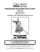
PRESSURE WASHER WITH CART 1300 PSI Model 47761 ASSEMBLY AND OPERATING INSTRUCTIONS ® 3491 Mission Oaks Blvd., Camarillo, CA 93011 Visit our Web site at: http://www.harborfreight.com TO PREVENT SERIOUS INJURY, READ AND UNDERSTAND ALL WARNINGS AND INSTRUCTIONS BEFORE USE. Copyright© 2005 by Harbor Freight Tools®. All rights reserved. No portion of this manual or any artwork contained herein may be reproduced in any shape or form without the express written consent of Harbor Freight Tools.
Contents Unpacking ................................................................................ 2 Specifications .......................................................................... 3 Safety ....................................................................................... 3 General Safety Rules ........................................................................3 Specific Safety Rules ........................................................................6 Grounding.....................
SPECIFICATIONS Electrical Requirements 120V / 13.0 AMPs / 60 Hz Single Phase / Two Prong GFCI Plug Power Cord Length/Type 31' / 16AWG X 2C Maximum Pressure 1300 PSI Maximum Capacity 1.6 GPM Water Supply Required 3-4 GPM minimum Lance Length 15-3/4" Gun Lance Length 13-1/4" E193752 High Pressure Hose Length 19 Ft. Accessories 10 oz. Detergent Bottle Tip Cleaner / Car t Assembly Weight 25.1 Pounds.
ELECTRICAL SAFETY 1. Grounded tools must be plugged into an outlet properly installed and grounded in accordance with all codes and ordinances. Never remove the grounding prong or modify the plug in any way. Do not use any adapter plugs. Check with a qualified electrician if you are in doubt as to whether the outlet is properly grounded. If the tools should electrically malfunction or break down, grounding provides a low resistance path to carry electricity away from the user. 2.
6. Use safety equipment. Always wear eye protection. Nonskid safety shoes, hard hat, or hearing protection must be used for appropriate conditions. Always wear ANSI approved safety impact goggles and thick rubber boots during use and maintenance. TOOL USE AND CARE 1. Use clamps (not included) or other practical ways to secure and support a smaller workpiece to a stable platform. Holding the work by hand or against your body is unstable and may lead to loss of control. 2. Do not force the tool.
SPECIFIC SAFETY RULES 1. Maintain a safe working environment. Keep the work area well lit. Make sure there is adequate surrounding workspace. Always keep the work area free of obstructions, grease, oil, trash, and other debris. Do not use the Pressure Washer in areas near flammable chemicals, dusts, and vapors. 2. Maintain labels and nameplates on the Pressure Washer. These carry important information. If unreadable or missing, contact Harbor Freight Tools for a replacement. 3.
14. Some chemicals or detergents may be harmful if inhaled or ingested. Use an ANSI approved respirator or mask whenever there is a chance that vapors may be inhaled. 15. Keep the High Pressure Hose connected to the Pressure Washer and Spray Gun while the system is pressurized. Disconnecting the Pressure Hose while the unit is pressurized is dangerous, and may cause injury. 16. Prior to starting the Pressure Washer in cold weather, check all of the parts of the unit to make sure ice has not formed.
GROUNDING WARNING! Improperly connecting the grounding wire can result in the risk of electric shock. Check with a qualified electrician if you are in doubt as to whether the outlet is properly grounded. Do not modify the power cord plug provided with the tool. Never remove the grounding prong from the plug. Do not use the tool if the power cord or plug is damaged. If damaged, have it repaired by a service facility before use.
EXTENSION CORDS 1. Grounded tools require a three wire extension cord. 2. As the distance from the supply outlet increases, you must use a heavier gauge extension cord. Using extension cords with inadequately sized wire causes a serious drop in voltage, resulting in loss of power and possible tool damage. (See Table A.) 3. The smaller the gauge number of the wire, the greater the capacity of the cord. For example, a 14 gauge cord can carry a higher current than a 16 gauge cord.
ASSEMBLY NOTE: For additional references to the parts listed in the following pages, refer to the Parts Diagrams on pages 18-21. 1. Slide the Cart Handle (A1) onto the Cart Base (A3), making sure the holes in the upper portion of the Handle face toward the rear of the Cart. (See Figure B.) 2. Align the mounting holes located at the bottom of the Handle (A1) with the mounting holes located at the top of the Cart Base (A3).
8. Remove the protective plastic caps from the unit’s water Inlet Port and water Outlet Port. (See Figure D.) 9. Ensure the inlet water strainer is free of debris. Firmly attach the Heavy Duty Hose Adapter (G) to the water Inlet Port. 10. Firmly attach the High Pressure Hose (26A) to the water Outlet Port.
Plug become necessary, only a qualified technician should perform the service. (See Figure E.) 3. The Pressure Washer is equipped with a Trigger Safety Lock (25A). When the Trigger (23A) is not squeezed, the Safety Lock should be pressed all the way in to help prevent children from using the tool. To disengage the Safety Lock, press the opposite side. (See Figure F.) SAFETY TRIGGER LOCK (25A) TRIGGER (23A) FIGURE F 4.
SETUP 1. CHECK THE WATER SUPPLY. Prior to using the Pressure Washer for the first time, it is ESSENTIAL to verify that the water supply is adequate. The Pressure Washer needs TWICE the water supply (or volume) than the stated water output (1.6 GPM). This Pressure Washer will need about 3-4 GPM to operate correctly and efficiently. If the water is being supplied by a well/pump, make certain that the well/pump produces enough water to keep up with the Pressure Washer’s water demands.
OPERATION 1. Make sure the Power Switch is in the “OFF” position. Attach the heavy duty hose to the Pressure Washer, using the Heavy Duty Hose Adapter (G). 3. Attach the Spray Lance (K) or Detergent Bottle (H) into the Spray Wand Extension (I), and press and twist the Wand into the Extension until the Wand locks in place. (See Figure C, page 10.) NOTE: The Pressure Washer will not pressurize if the Nozzle is not completely assembled. It will not work properly with only part of the Wand installed. 4.
IMPORTANT! NEVER ALLOW THE UNIT TO SIT IDLE WITH THE SWITCH ON FOR LONGER THAN TWO MINUTES. OPERATING TIPS BECOME FAMILIAR WITH YOUR MACHINE 1. Before beginning work, set aside enough time to familiarize yourself with this machine’s cleaning rate and capacity along with all instructions and precautions contained in this section, along with the Operating Instruction and Operating Controls sections. 2. This unit is intended for various light to moderate cleaning applications.
CLEANING RECOMMENDATIONS 1. Clean an inconspicuous test area to help avoid damaging the surface: Always begin with the fan spray at a distance of about 3-5 feet from the surface being cleaned to avoid damaging the surface of the object. Make sure that the test area is clear of people and water prone/delicate objects. If a pressure washing detergent is to be used, apply the detergent to this area as well.
INSPECTION, MAINTENANCE, AND CLEANING 1. WARNING! Make sure that 1) the Trigger is locked in its off position, 2) the Power Switch of the Pressure Washer is in its “OFF” position, 3) the plug is unplugged from its electrical outlet, 4) that the water supply is shut off, and 5) all residual water pressure is safely expelled before performing any inspection, maintenance, or cleaning procedures. Point the Gun Assembly (E) in a safe direction and discharge all remaining pressure.
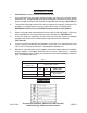
PARTS LISTS AND DIAGRAMS MAIN PARTS LIST Part Description 1 Handle 2 3 1 HeadD Pump 1 Seal (Piston “Y” Cup)D (Inlet)D 3 Description 33 Switches (Special Use) 34 Screw 35 Cap Q'ty Part Description Q'ty 1 65 Air FilterD 1 9 PinD 2 66 1 67 Pump GearD BodyD 1 4 Check Valve 3 36 Seal 1 68 5 O-RingD 3 37 Slip On Receptacle 7 69 BearingD 1 6 SpringD 3 38 Sleeve 8 70 Bolt (ST3.
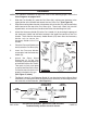
94 93 81 34 82 89 73 F 76 74 57 56 20 8 7 2 4 5 3 6 23 24 25 22 15 14 13 12 17 44 11 1 10 9 29 31 30 32 33 28 39 40 37 38 36 35 34 37 41 38 42 D 43 16 52 45 46 47 48 70 23 53 49 50 51 71 19 18 21 26 27 55 54 58 59 60 61 75 62 63 F 72 64 77 C 65 37, 38 66 67 68 78 69 80 83 79 92 84 85 86 95 87 88 90 91 37 38 MAIN PARTS DIAGRAM C = This part is included in the Motor Assembly (C).
PARTS LIST AND DIAGRAM A Part Description 1A Casing 2A Casing (Left)E 3A SpringE 4A O-RingE 5A Q'ty (Right)E Back Up 18A 1 1 19A NozzleK 1 2 20A LamellaK 1 21A PinK 1 22A U-PinK 1 1 6A Piston 1 23A TriggerE 7A O-RingE 1 24A Self Tapping ScrewE 6 8A SpringE, K 2 25A Safety LockE 1 9A O-RingE, K 10A Valve BodyE 11A Spray Wand 12A ExtensionJ TurnbuckleE 13A Spray WandK 14A Blade CompressorK 15A O-RingK 16A KnobK HoseE 2 26A High Pressure 1 27A Ja
ASSEMBLY PARTS LIST AND DIAGRAM Assembly A Description Car t Assembly Q'ty Assembly 1 Handle 1 A2 Accessor y Holder Band 2 A3 Base 1 F A4 Bolt 2 A5 Wing Nut 2 Q'ty Trigger and Gun Assembly with High Pressure Hose E A1 Description 1 (Par ts 1A-10A, 12A, 23A-33A) Housing (Par ts 72 & 92) 1 G Heavy Duty Hose Adapter 1 H Detergent Sprayer 1 B Accessory Hook 1 I Tip Cleaner 1 C Motor Assembly (Par t 77) 1 J Spray Wand Ext.
TROUBLESHOOTING IMPORTANT! Be CERTAIN to shut off the Pressure Washer, release all pressure in a safe manner, and disconnect it from power and water before adjusting, cleaning, or repairing the unit. PRESSURE WASHER STOPS SUDDENLY The thermal safety Switch may be tripped. Switch the unit off and allow the unit to rest for 20-30 minutes and try again. UNIT OPERATES NORMALLY AFTER RESTING The following points should be applied to help reduce the frequency of rest periods: 1.
TROUBLESHOOTING (CONTINUED) IMPORTANT! Be CERTAIN to shut off the Pressure Washer, release all pressure in a safe manner, and disconnect it from power and water before adjusting, cleaning, or repairing the unit. PRESSURE WASHER WILL NOT START Dry self thoroughly and check the voltage at the outlet, and the reset button on the GFCI power plug (explained under Controls and Features, #2 on page 11). POWER SUPPLY INADEQUATE Have a certified electrician correct the problem.
TROUBLESHOOTING (CONTINUED) IMPORTANT! Be CERTAIN to shut off the Pressure Washer, release all pressure in a safe manner, and disconnect it from power and water before adjusting, cleaning, or repairing the unit. PRESSURE CHANGES DURING USE Air may be getting in the water supply hose, check all connections. CONNECTIONS ARE LOOSE ALL CONNECTIONS ARE TIGHT Retighten connections. Check that tip is free from debris and deposits. TIP IS CLEAN TIP IS DIRTY Clean tip, using the included Tip Cleaner (I).