
Product manual


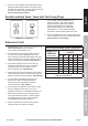


Page 10 For technical questions, please call 1-800-444-3353. Item 69702
SAFETY OPERATION MAINTENANCESETUP
Operating Instructions
Read the ENTIRE IMPORTANT SAFETY INFORMATION section at the beginning of this
manual including all text under subheadings therein before set up or use of this product.
Tool Set Up
TO PREVENT SERIOUS INJURY FROM ACCIDENTAL OPERATION:
Make sure that the Trigger is in the off-position and unplug the tool from its
electrical outlet before performing any procedure in this section.
TO PREVENT SERIOUS INJURY FROM FLYING FRAGMENTS:
Do not use abrasive or masonry-cutting blades. The guards of this saw are
not designed to protect against the failure of such blades.
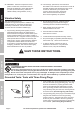
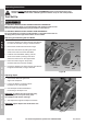
Removing and Installing the Saw Blade
1. Hold in the Spindle Lock while using the Hex Wrench
to loosen the Hex Bolt, turning it counterclockwise.
2. Remove the Hex Bolt and the Outer Flange.
3. Open the Lower Guard by raising the Lower
Guard Lever and remove the Saw Blade.
4. Install the new Saw Blade, making sure the
arrow on the blade is pointing in the same
direction as the arrow on the Upper Guard.
5. Place the Outer Flange on the spindle,
recessed side first. Insert the Hex Bolt.
6. Hold in the Spindle Lock while using the Hex Wrench
to tighten the Hex Bolt, turning it clockwise.
Figure B
Adjusting Depth
1. Set the Base Plate flat against the
edge of the workpiece.
2. Loosen the Depth Lock Knob to allow
the depth of cut to be adjusted.
3. Use the Depth Scale located behind
the housing to set depth of cut.
WARNING! To reduce the risk of serious injury,
adjust the depth of cut to just barely clear
the workpiece and remove shavings.
4. After adjustment, tighten the Depth Lock Knob.
WARNING! Tighten Depth Lock Knob before use.
Figure C
Spindle Lock
Hex
Bolt
Hex
Wrench
Saw Blade
Outer
Flange
Lower Guard
Lever
Base
Plate
Depth Lock
Knob
Depth
Scale