Table of Contents Safety.......................................................... 2 Maintenance............................................... 14 Setup........................................................... 6 Parts List and Diagram............................... 19 Specifications.............................................. 6 Warranty..................................................... 23 SAFETY Operation.....................................................
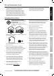
Set up Precautions (cont.) 10. Do not operate the Generator before grounding. The Generator must be earth-grounded in accordance with all relevant electrical codes and standards before operation. SAFETY 9. Improper connections to a building electrical system can allow electrical current from the generator to backfeed into the utility lines.
Operating Precautions (cont.) 16. Connect the Generator only to a load or electrical system (120 volt or 240 volt) that is compatible with the electrical characteristics and rated capacities of the Generator. SAFETY 17. Insulate all connections and disconnected wires. 29. Stay alert, watch what you are doing and use common sense when operating this piece of equipment. Do not use this piece of equipment while tired or under the influence of drugs, alcohol or medication. 18. Guard against electric shock.
b. Turn the engine switch to its “OFF” position. c. Allow the engine to completely cool. d. Then, remove the spark plug cap from the spark plug. 2. Keep all safety guards in place and in proper working order. Safety guards include muffler, air cleaner, mechanical guards, and heat shields, among other guards. 9. Store equipment out of the reach of children. 10. Follow scheduled engine and equipment maintenance. 3.
Functional Description Specifications SAFETY Rated Output Generator Electrical Receptacle Displacement Engine Type Cooling System Engine Type Capacity Fuel Engine Oil Type SAE SETUP Capacity Run Time @ 50% load Operational Volume Available accessories 120/240V~, 60Hz 5,500 Watts (6,500 max) Two 3-Prong, duplex NEMA #5-20 120V One 4-Prong, NEMA #L14-30 twistlock 120V/240V One DC Outlet 12VDC 420cc Horizontal Single Cylinder 4 stroke OHV EPA phase III compliant Forced air cooled 87+ octane unleaded
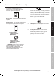
Components and Controls (cont.) I O ON OFF 3. Circuit Breakers: The circuit breaker protects the Generator from overloading. The rating of the breaker and the load it protects are marked near the breaker. Should any of the Circuit Breakers trip, the Generator will stop the electricity output. If this happens, unplug all loads from the Generator. Allow the Generator to cool down. Then, press the tripped Circuit Breaker, restart the Engine, and re-attach loads.
Initial Tool Set Up/Assembly SAFETY Read the ENTIRE IMPORTANT SAFETY INFORMATION section at the beginning of this manual including all text under subheadings therein before set up or use of this product. Note: For additional information regarding the parts listed in the following pages, refer to the Assembly Diagram near the end of this manual.
4. Reinsert the Dipstick without threading it in and remove it to check the oil level. The oil level should be up to the full level as shown above. 5. If the oil level is at or below the low mark add the appropriate type of oil until the oil level is at the proper level. SAE 10W‑30 oil is recommended for general use. (The SAE Viscosity Grade chart on page 15 in the User‑Maintenance Instructions section shows other viscosities to use in different average temperatures.) 6.
Starting the Engine 1. To start a cold engine, move the Choke to the CHOKE position. To restart a warm engine, leave the Choke in the RUN position. SAFETY 2. Open the Fuel Valve. SETUP 3. Turn the Engine Switch to ON. I ON O OPERATION 4. Grip the Starter Handle of the Engine loosely and pull it slowly several times to allow the gasoline to flow into the Engine’s carburetor. Then pull the Starter Handle gently until resistance is felt. Allow Cable to retract fully and then pull it quickly.
Connecting Electrical Loads Familiarize yourself with the engine controls, power panel and how to start the engine before using the generator. Calculate the wattage of the products you will use with the generator and verify that the generator can handle the total load. SAFETY WARNING! Connect only properly wired plugs to the generator. A plug that is spliced onto a different cord may be hazardous. Only a qualified electrician should wire a plug onto a cord.
Calculating Total Wattage of Devices Used with the Generator SAFETY Before using the Generator, check that the products you want to plug into the unit are below the rated and maximum wattage ratings of the Generator. Use the Wattage Calculation Table below, and the watts listed on your products, to help calculate multiple wattage totals. Wattage Estimate Charts Note: Wattages listed below are estimates for that type of equipment only. Check nameplate wattages on all loads before connecting to Generator.
1. To stop the engine in an emergency, turn the Engine Switch off. I NOTICE: Generator shut-off under load may damage the generator and attached equipment. O OFF SAFETY Stopping the Engine in an Emergency Stopping the Engine Under Normal Conditions SETUP 1. Before turning off the Engine, turn off all electrical loads, then unplug them. 2. Turn the Engine Switch off. O OPERATION I OFF MAINTENANCE 3. Close the Fuel Valve.
User‑Maintenance Instructions SAFETY TO PREVENT SERIOUS INJURY FROM ACCIDENTAL OPERATION: Turn the Power Switch of the generator to its “OFF” position, wait for the engine to cool, and disconnect the spark plug cap before performing any inspection, maintenance, or cleaning procedures. TO PREVENT SERIOUS INJURY FROM EQUIPMENT FAILURE: Do not use damaged equipment. If abnormal noise, vibration, or excess smoking occurs, have the problem corrected before further use.
WARNING! TO PREVENT SERIOUS INJURY FROM FIRE: Fill the fuel tank in a well-ventilated area away from ignition sources. If the engine is hot from use, shut the engine off and wait for it to cool before adding fuel. Do not smoke. Note: Do not use gasoline containing more than 10% ethanol (E10). Do not use E85 ethanol. 1. Clean the Fuel Cap and the area around it. 4. Replace the Fuel Cap. 2. Unscrew and remove the Fuel Cap. 5. Wipe up any spilled fuel and allow excess to evaporate before starting engine.
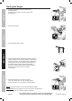
Spark Plug Maintenance 1. Disconnect spark plug cap from end of plug. Clean out debris from around spark plug. SAFETY 2. Using a spark plug wrench, remove the spark plug. Spark Plug 3. Inspect the spark plug: If the electrode is oily, clean it using a clean, dry rag. If the Cylinder electrode has deposits Assembly on it, polish it using emery paper. If the white insulator is cracked or chipped, the spark plug needs to be replaced. SETUP NOTICE: Using an incorrect spark plug may damage the engine.
Troubleshooting FUEL RELATED: FUEL RELATED: 1. No fuel in tank or fuel valve closed. 1. Fill fuel tank and open fuel valve. 2. Choke not in CHOKE position, cold engine. 2. Move Choke to CHOKE position. 3. Gasoline with more than 10% ethanol used. 3. Clean out ethanol rich gasoline from fuel (E15, E20, E85, etc.) system. Replace components damaged by ethanol. Use fresh 87+ octane unleaded gasoline only. Do not use gasoline with more than 10% ethanol (E15, E20, E85, etc.). 4.
Troubleshooting (cont.) Problem Engine misfires Possible Causes SAFETY 1. Spark plug cap loose. 1. Check wire connections. 2. Incorrect spark plug gap or damaged spark plug. 2. Re-gap or replace spark plug. 3. Defective spark plug cap. 3. Replace spark plug cap. 4. Old or low quality gasoline. 4. Use only fresh 87+ octane unleaded gasoline. Do not use gasoline with more than 10% ethanol (E15, E20, E85, etc.). 5. Incorrect compression. Engine stops suddenly Probable Solutions 5.
Parts List and Diagram THE MANUFACTURER AND/OR DISTRIBUTOR HAS PROVIDED THE PARTS LIST AND ASSEMBLY DIAGRAM IN THIS MANUAL AS A REFERENCE TOOL ONLY. NEITHER THE MANUFACTURER OR DISTRIBUTOR MAKES ANY REPRESENTATION OR WARRANTY OF ANY KIND TO THE BUYER THAT HE OR SHE IS QUALIFIED TO MAKE ANY REPAIRS TO THE PRODUCT, OR THAT HE OR SHE IS QUALIFIED TO REPLACE ANY PARTS OF THE PRODUCT.
Parts List (cont.) Part SAFETY SETUP OPERATION 87 88 89 90 91 92 93 94 95 96 97 98 99 100 101 102 103 104 105 106 107 108 109 110 111 112 113 114 115 116 117 118 119 120 121 122 123 124 Description Grommet, Crankcase Bolt, Flange Stay Comp., Muffler Seal, Protector Muffler Protector Comp., Muffler Inner Muffler Assy. Protector, Muffler Side Bolt, Flange, 6×14 Protector Comp., Muffler Outer Gasket, Ex., Pipe Pipe, Comp., Ex. Gasket, Ex., Pipe Nut, Hex., M8 Bolt, Flange, 8×32 Fuel Tank Cock Comp.
MAINTENANCE OPERATION SETUP SAFETY Assembly Diagram Item 69672 / 69674 For Generator technical questions, please call 1-800-444-3353. For Engine technical questions, please call 1-800-520-0882.
Assembly Diagram (cont.) SAFETY SETUP OPERATION Note: Parts 114-117 and 141-143 are only on Item 69674 (EPA/CARB version) MAINTENANCE Page 22 For Generator technical questions, please call 1-800-444-3353. For Engine technical questions, please call 1-800-520-0882.
Harbor Freight Tools Co. makes every effort to assure that its products meet high quality and durability standards, and warrants to the original purchaser that this product is free from defects in materials and workmanship for the period of 90 days from the date of purchase.
If you have any questions regarding your warranty rights and responsibilities, you should contact the Harbor Freight Tools Customer Service Department at 1-800-444-3353. Harbor Freight Tools Emission Control Defects Warranty Provisions 1.