Owner’s Manual & Safety Instructions Save This Manual Keep this manual for the safety warnings and precautions, assembly, operating, inspection, maintenance and cleaning procedures. Write the product’s serial number in the back of the manual near the assembly diagram (or month and year of purchase if product has no number). Keep this manual and the receipt in a safe and dry place for future reference. REV 15e Using an engine indoors CAN KILL YOU IN MINUTES. Engine exhaust contains carbon monoxide.
Table of Contents Specifications.............................................. 2 Safety ��������������������������������������������������������� 3 Setup........................................................... 6 Operationr��������������������������������������������������� 16 Maintenances���������������������������������������������� 20 Troubleshooting.......................................... 24 Warranties.................................................. 26 Parts Lists and Diagrams....................
WARNING SYMBOLS AND DEFINITIONS This is the safety alert symbol. It is used to alert you to potential personal injury hazards. Obey all safety messages that follow this symbol to avoid possible injury or death. Safety Indicates a hazardous situation which, if not avoided, will result in death or serious injury. Indicates a hazardous situation which, if not avoided, could result in death or serious injury. Indicates a hazardous situation which, if not avoided, could result in minor or moderate injury.
Set up Precautions Safety 1. Gasoline fuel and fumes are flammable, and potentially explosive. Use proper fuel storage and handling procedures. Do not store fuel or other flammable materials nearby. 4. Set up and use only on a flat, level, well‑ventilated surface. 2. Have multiple ABC class fire extinguishers nearby. 6. Use only lubricants and fuel recommended in the Specifications chart of this manual. 3. Operation of this equipment may create sparks that can start fires around dry vegetation.
22. Do not operate the equipment with known leaks in the engine’s fuel system. 23. WARNING: This product contains or, when used, produces a chemical known to the State of California to cause cancer and birth defects or other reproductive harm. (California Health & Safety Code § 25249.5, et seq.) 24. When spills of fuel or oil occur, they must be cleaned up immediately. Dispose of fluids and cleaning materials as per any local, state, or federal codes and regulations.
Set Up Read the ENTIRE IMPORTANT SAFETY INFORMATION section at the beginning of this manual including all text under subheadings therein before set up or use of this product. Safety TO PREVENT SERIOUS INJURY: Operate only with proper spark arrestor installed. Operation of this equipment may create sparks that can start fires around dry vegetation. A spark arrestor may be required. The operator should contact local fire agencies for laws or regulations relating to fire prevention requirements.
Components and Controls Muffler Safety Oil Fill Plug Lifting Bracket Setup Spark Plug (1 of 2) Dipstick Starter Operation Air Cleaner Lifting Bracket Choke Spark Plug (2 of 2) Throttle Radiator Circuit Breaker ITEM 61614 For technical questions, please call 1-888-866-5797.
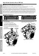
High Altitude Operation Above 3000 feet WARNING! TO PREVENT SERIOUS INJURY FROM FIRE: Follow instructions in a well-ventilated area away from ignition sources. If the engine is hot from use, shut the engine off and wait for it to cool before proceeding. Do not smoke. Safety NOTICE: Warranty void if necessary adjustments are not made for high altitude use.
Air Cleaner Top Cover (142b) 9. Remove the four Shroud Nuts (99) and the two Flange Shoulder Bolts (112) from the Shroud (100). The Flange Shoulder Bolt on the right holds the Lifting Bracket (111) in place. See Figure E. Flange Shoulder Bolt (112) Flange Shoulder Bolt (112) behind Lifting Bracket Air Cleaner Spacer (142c) Safety 5. Remove the Air Cleaner Top Cover (142b) and internal Air Cleaner components (Spacer, Foam and Paper Filters (142c-142e)). See Figure C.
11. WARNING! TO PREVENT SERIOUS INJURY FROM FIRE, BEFORE CONTINUING: a. Make sure that the work area is well‑ventilated and that there are no ignition sources. b. Have multiple class ABC fire extinguishers available. c. Double-check that fuel hose leading from fuel tank to Fuel Filter is clamped or fuel valve is closed. Safety d. Use a safe, proper means to clean up all fuel spills immediately. 12. Squeeze the Spring Clamp (140) and slide it back.
20. Underneath where the Fuel Pump Bracket was, the Solenoid Valve (138) is connected. Note the location of the green wire and green dot on the connector. Unplug the connector. See Figure L. Carburetor Intake Elbow (131) Fuel Pump Bracket (40) Bolt (132) Bolt (133) Bolt (132) Safety 19. At the front of the Carburetor, remove the Bolt (38) holding the Fuel Pump Bracket (40) in place. See Figure K.
23. Hold the fuel drain port over a bowl, and open the Carburetor Drain Plug (137a) to allow fuel to drain out of that port. Once the carburetor is empty, close the Carburetor Drain Plug. See Figure M. 26. Use a carburetor screwdriver (sold separately) to remove the Left Main Jet and replace it with the proper replacement Left Main Jet (A1 or A3) for the altitude. See Figure O. Safety 27.
Reassembly 1. Replace the Outer and Inner Bowl O-rings (137d, 137e) with the replacements from the altitude kit. Do not reuse existing O-rings. 5. Attach the Choke Rod on the right side of the Carburetor, and secure it with its Clip. [#17,18] 6. Attach the Breather Hose to the Carburetor, and secure it with its Clamp. [#16] 7. Attach the Throttle Rod Spring to the Throttle Rod Clip on the left side of the Carburetor. [#15] Inner Bowl O-ring 8.
Battery Setup Instructions Safety 1. Place a fully charged, lead-acid 12 volt, 36 Ah battery (not included) in a stable, flat location near the engine. solenoid on Starter (164) 2. Only use cables sized to match their length according to . red wire to positive battery cable (lower gauge numbers mean thicker cables) Cable Gauge Maximum Cable Length 6 4 2 5′ 7′ 12′ connect negative battery cable to a mounting bolt Table A: Minimum Cable Diameters Setup 3.
Fuel Tank Setup Instructions 3. Connect a fuel hose from the fuel tank to the exposed port of the Fuel Filter, and secure it in place with a hose clamp. See Figure S. fuel hose connection Setup 2. WARNING! Fuel tank (not included) must be designed specifically for containing gasoline and must be mounted to a stable mounting frame. Some areas may have specific gasoline vapor containment requirements; comply with local, state, and federal laws. Safety 1.
Operation Read the ENTIRE IMPORTANT SAFETY INFORMATION section at the beginning of this manual including all text under subheadings therein before set up or use of this product. Safety Pre-Start Checks Inspect engine and equipment looking for damaged, loose, and missing parts before set up and starting. If any problems are found, do not use equipment until fixed properly.
Checking and Filling Fuel 1. Clean the Fuel Cap and the area around it. 2. Unscrew and remove the Fuel Cap. 3. Remove the Strainer and remove any dirt and debris. Then replace the Strainer. 4. If needed, fill the Fuel Tank to about 1 inch under the fill neck of the Fuel Tank with 87 octane or higher unleaded gasoline that has been treated with a fuel stabilizer additive. Follow fuel stabilizer manufacturer’s recommendations for use. 5. Then replace the Fuel Cap. 6.
Starting the Engine Safety Before starting the engine: a. Follow the Set Up Instructions in this manual to prepare the engine. b. Follow the Set Up Instructions in the equipment manual to prepare the equipment. c. Inspect the equipment and engine. d. Fill the engine with the proper amount and type of both unleaded gasoline and oil. e. Read the Equipment Operation section in the equipment manual. 1. To start a cold engine, pull the Choke Knob out to the START position.
5. Allow the Engine to run for several seconds. Then, if the Choke Knob is in the pulled‑out START position, push the Choke Knob in very slowly to its RUN position. Safety 5 Note: Moving the Choke Knob too fast could stall the engine. IMPORTANT: Allow the engine to run at no load for five minutes after each start‑up so that the engine can stabilize. 6. Adjust the Throttle as needed. Setup Break-in Period: a. Breaking-in the engine will help to ensure proper equipment and engine operation. b.
Maintenance WARNING Safety TO PREVENT SERIOUS INJURY FROM ACCIDENTAL STARTING: Turn the Power Switch of the equipment to its “OFF” position, wait for the engine to cool, and disconnect the spark plug caps before performing any inspection, maintenance, or cleaning procedures. TO PREVENT SERIOUS INJURY FROM EQUIPMENT FAILURE: Do not use damaged equipment. If abnormal noise, vibration, or excess smoking occurs, have the problem corrected before further use. Follow all service instructions in this manual.
Checking and Filling Fuel 1. Clean the Fuel Cap and the area around it. 2. Unscrew and remove the Fuel Cap. 3. Remove the Strainer and remove any dirt and debris. Then replace the Strainer. Note: Do not use gasoline containing more than 10% ethanol (E10). Do not use E85 ethanol. Add fuel stabilizer to the gasoline or the Warranty is VOID. Note: Do not use gasoline that has been stored in a metal fuel container or a dirty fuel container.
Air Filter Maintenance 1. Remove the Air Cleaner Top Cover and the air filter elements and check for dirt. Clean as described below. Safety 2. Clean Paper Air Filter: To prevent injury from dust and debris, wear ANSI‑approved safety goggles, NIOSH‑approved dust mask/respirator, and heavy-duty work gloves. In a well‑ventilated area away from bystanders, use pressurized air to blow dust out of the Filter. 3. Clean Foam Air Filter: Wash the Filter in warm water and mild detergent several times. Rinse.
When the equipment is to remain idle for longer than 20 days, prepare the Engine for storage as follows: c. Replace spark plug, but leave spark plug cap disconnected. 1. CLEANING: Wait for Engine to cool, then clean Engine with dry cloth. NOTICE: Do not clean using water. The water will gradually enter the Engine and cause rust damage. Apply a thin coat of rust preventive oil to all metal parts. d. Pull Starter Handle to distribute oil in cylinder.
Troubleshooting Problem Possible Causes Engine will not start FUEL RELATED: Probable Solutions FUEL RELATED: Safety Setup Operation Maintenance 1. No fuel in tank or fuel valve closed. 1. Fill fuel tank with fresh 87+ octane stabilizer-treated unleaded gasoline and open fuel valve. Do not use gasoline with more than 10% ethanol (E15, E20, E85, etc.). 2. Choke not in START position, cold engine. 2. Move Choke to START position. 3. Gasoline with more than 10% ethanol used. (E15, E20, E85, etc.
1. Spark plug caps loose. 1. Check wire connections. 2. Incorrect spark plug gaps or damaged spark plugs. 2. Re-gap or replace spark plugs. 3. Defective spark plug caps. 3. Replace spark plug caps. 4. Old or low quality gasoline. 4. Use only fresh 87+ octane stabilizer-treated unleaded gasoline. Do not use gasoline with more than 10% ethanol (E15, E20, E85, etc.). 5. Incorrect compression. 5. Diagnose and repair compression. (Use Engine will not start: COMPRESSION RELATED section.) 1.
Warranties Safety Limited 90 Day Warranty Harbor Freight Tools Co. makes every effort to assure that its products meet high quality and durability standards, and warrants to the original purchaser that this product is free from defects in materials and workmanship for the period of 90 days from the date of purchase.
HFT warrants to a first retail purchaser and each subsequent purchaser that the engine is free from defects in materials and workmanship that cause the failure of warranted parts for a period of two (2) years after the date of delivery to the first retail purchaser. 2. No Charge Repair or Replacement Repair or replacement of any warranted part will be performed at no charge to the owner if the work is performed through a warranty station authorized by HFT.
Parts Lists and Diagrams Parts List Safety Part Setup Operation Maintenance 1 2 3 4 5 6 7 8 9 10 11 12 13 14 15 16 17 18 19 20 21 22 23 24 25 26 27 28 29 30 31 32 33 34 35 36 37 38 39 40 41 42 43 44 45 46 47 48 49 50 51 52 53 54 55 56 57 58 59 60 61 62 63 64 65 66 Description Bolt, Cylinder Head Cover Cover, Left Cylinder Head Gasket, Cylinder Head Cover Spark Plug Bolt, Cylinder Head Head, Left Cylinder Head, Right Cylinder Pin Gasket, Cylinder Head Metal Head Gasket Stud Stud Cover, Right Cylinder H
Safety 55 57 71 65 69 62 61 60 61 70 59 184 184 78 79 80 186 75 77 184 185 184 185 74 107 103 107 105 107 109 107 122 124 1 187 183 186 77 75 114 111 113 107 4 3 5 77 78 79 80 82 82 83 107 107 104 107 107 112 127 76 81 81 2 73 Setup 53 56 56 63 63 62 76 111 106 110 77 125 108 122 115 123 120 121 122 5 12 5 83 5 12 84 84 85 6 85 89 8 8 90 72 89 88 89 87 87 88 89 128 12 90 12 91 86 9 8 91 14 15 5 13 3 5 1 4 5 11 11 11 7
Mounting Hole Diagram Note: Not to scale. Safety 7.7" / 195.5mm 4" / 101.5mm 3.375" / 86mm ~4" / 102mm 4.625" / 117.5mm Setup 2x 0.47" / 12mm 4x 0.47" / 12mm Operation Maintenance Page 30 For technical questions, please call 1-888-866-5797.
Power Take-Off Diagram 2.84" / 72.2mm 0.72" / 18.3mm 1.3" / 34mm 3/8" - 24UNF 2.375" / 60.5mm 9x 0.43" / 11mm Safety Note: Not to scale. 0.2" / 5mm 1.1" / 28mm 1.4" / 36mm 0.86" / 21.8mm 0.25" / 6.3mm Setup PTO Ø5.75" / 146mm Operation 5.3" / 135mm 1" / 25.4mm Ø5" / 127mm 4x 5/16" - 24UNF 4x 3/8" - 16UNC Ø7.75" / 196.9mm Ø6.5" / 165.1mm Maintenance 4x 7/16" - 14UNC ITEM 61614 For technical questions, please call 1-888-866-5797.
3491 Mission Oaks Blvd.