Table of contents SAFETy Safety ......................................................... 2 Maintenance .............................................. 14 Specifications ............................................. 7 Setup .......................................................... 9 Operation ................................................... 12 Parts List and Diagram .............................. 18 Warranty ....................................................
IMpORTANT SAFETy INSTRUcTIONS SAFETy INSTRUcTIONS pERTAINING TO A RISK OF FIRE, ELEcTRIc SHOcK, OR INJURy TO pERSONS WARNING – When using tools, basic precautions should always be followed, including the following: General To reduce the risks of electric shock, fire, and injury to persons, read all the instructions before using the tool. Work Area a. Keep the work area clean and well lighted. Cluttered benches and dark areas increase the risks of electric shock, fire, and injury to persons. c.
Tool Use and care SAFETy a. Use clamps or another practical way to secure and support the workpiece to a stable platform. Holding the work by hand or against the body is unstable and can lead to loss of control. b. Do not force the tool. Use the correct tool for the application. The correct tool will do the job better and safer at the rate for which the tool is designed. c. Do not use the tool if the trigger does not turn the tool on or off.
Specific Safety Instructions 3. choice of triggering method is important. check manual for triggering options. 4. Always assume the tool contains fasteners. SAFETy 19. Hold tool away from head and body. During operation the tool may kick back causing injury. 20. Do not fire fasteners into a workpiece that has people, utility lines, or other objects behind or inside it. 6. Do not actuate the tool unless the tool is placed firmly against the workpiece. 22.
Vibration precautions SAFETy This tool vibrates during use. Repeated or long-term exposure to vibration may cause temporary or permanent physical injury, particularly to the hands, arms and shoulders. To reduce the risk of vibration-related injury: 1. Anyone using vibrating tools regularly or for an extended period should first be examined by a doctor and then have regular medical check-ups to ensure medical problems are not being caused or worsened from use.
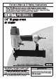
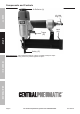
Functional Description 120 PSI Air Inlet 1/4″ - 18 NPT Safety Mechanism Type Single Sequential Staple Type 5/8” to 1-1/2”, 18 Gauge, 1/4” Crown Staples Magazine Capacity 100 Pieces MAINTENANcE OpERATION SETUp Maximum Air Pressure SAFETy Specifications Item 68018 For technical questions, please call 1-800-444-3353.
components and controls Air Deflector (3) SAFETy Air Inlet Plug (72) Trigger (32) Latch (63) SETUp Safety (37) Safety Nosepiece - Also called the workpiece contact, the Safety Nosepiece helps prevent the tool from firing unless it is pressed against an object. OpERATION MAINTENANcE Page 8 For technical questions, please call 1-800-444-3353.
Initial Tool Set Up/Assembly Read the ENTIRE IMpORTANT SAFETy INFORMATION section at the beginning of this manual including all text under subheadings therein before set up or use of this product. SAFETy Note: For additional information regarding the parts listed in the following pages, refer to the Assembly Diagram near the end of this manual. Air Supply TO pREVENT EXpLOSION: Use only clean, dry, regulated, compressed air to power this tool.
Description Non-lubricated Tools A Air Hose Filter Regulator Lubricator (optional) Coupler and Plug Leader Hose (optional) Air Cleaner / Dryer (optional) Air Adjusting Valve (optional) MAINTENANcE A B C D E F G H OpERATION Lubricated Tools SETUp B B c c A Function A E E F H Connects air to tool Prevents dirt and condensation from damaging tool or workpiece Adjusts air pressure to tool For air tool lubrication Provides quick connection and release Increases coupler life Prevents water vapo
Item 68018 For technical questions, please call 1-800-444-3353.
Operating Instructions Read the ENTIRE IMpORTANT SAFETy INFORMATION section at the beginning of this manual including all text under subheadings therein before set up or use of this product. SAFETy Inspect tool before use, looking for damaged, loose, and missing parts. If any problems are found, do not use tool until repaired. Workpiece and Work Area Set Up 1. Designate a work area that is clean and well-lit. The work area must not allow access by children or pets to prevent distraction and injury. 2.
TO pREVENT SERIOUS INJURy FROM AccIDENTAL OpERATION, BEFORE LOADING: • Wear ANSI-approved safety goggles with side shields. Other people in the work area must also wear ANSI-approved impact safety goggles with side shields. • Release the trigger. • Detach the air supply. • Attempt to fire the Tool into a piece of scrap wood to ensure that it is disconnected and is incapable of firing any fasteners. 1.
User-Maintenance Instructions procedures not specifically explained in this manual must be performed only by a qualified technician. SAFETy TO pREVENT SERIOUS INJURy FROM AccIDENTAL OpERATION, BEFORE ANy MAINTENANcE OR REpAIRS ARE DONE (including clearing jams): • Wear ANSI-approved safety goggles with side shields. Other people in the work area must also wear ANSI-approved impact safety goggles with side shields. • Release the trigger. • Detach the air supply.
TO pREVENT SERIOUS INJURy FROM AccIDENTAL OpERATION, BEFORE ANy MAINTENANcE OR REpAIRS ARE DONE (including clearing jams): • Wear ANSI-approved safety goggles with side shields. Other people in the work area must also wear ANSI-approved impact safety goggles with side shields. • Release the trigger. • Detach the air supply. • Attempt to fire the Tool into a piece of scrap wood to ensure that it is disconnected and is incapable of firing any fasteners. • Empty the magazine and leave it open during service.
Troubleshooting problem Insufficient fastener depth. possible causes 1. Incorrect tool depth setting. 2. Not enough air pressure. SAFETy 3. Incorrect lubrication or not enough lubrication. 4. Blocked air inlet screen (if equipped). 5. Mechanism contaminated. Likely Solutions 1. Adjust depth setting, if available. 2. Check for loose connections and make sure that air supply is providing enough air pressure (PSI) to the tool’s air inlet. Do not exceed maximum air pressure. 3.
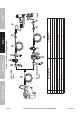
SETUp THE MANUFACTURER AND/OR DISTRIBUTOR HAS PROVIDED THE PARTS LIST AND ASSEMBLY DIAGRAM IN THIS MANUAL AS A REFERENCE TOOL ONLY. NEITHER THE MANUFACTURER OR DISTRIBUTOR MAKES ANY REPRESENTATION OR WARRANTY OF ANY KIND TO THE BUYER THAT HE OR SHE IS QUALIFIED TO MAKE ANY REPAIRS TO THE PRODUCT, OR THAT HE OR SHE IS QUALIFIED TO REPLACE ANY PARTS OF THE PRODUCT.
parts List and Diagram parts List SAFETy part SETUp OpERATION 1 2 3 4 5 6 7 8 9 10 11 12 13 14 15 16 17 18 19 20 21 22 23 24 25 26 27 28 29 30 31 32 33 34 35 36 Description Screw Air Deflector Spring Air Deflector Hex Bolt (M5x20) Spring Gasket Cylinder Cap Sealing Gasket Head Valve Spring O-Ring (13.7x2.4) Head Valve Head Valve Washer O-Ring (31.2x2.5) O-Ring (24.8x3.5) Collar O-Ring (42.6x2.35) O-Ring (21x3) Piston Assembly O-Ring (30x1.
MAINTENANcE OpERATION SETUp SAFETy Assembly Diagram Item 68018 For technical questions, please call 1-800-444-3353.
Limited 90 Day Warranty Harbor Freight Tools Co. makes every effort to assure that its products meet high quality and durability standards, and warrants to the original purchaser that this product is free from defects in materials and workmanship for the period of 90 days from the date of purchase.