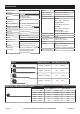
Specifications Rated Single Line Pull 5,000 lb. (2268 kg.) Application ATV/UTV Motor 12VDC 1.5 HP Permanent Magnet Power IN & Power OUT Battery 12VDC, Minimum 12 Ah Battery Cables 6 gauge, 6′ (1.83m) long Solenoid Cables 6 gauge, 3′ (0.92m) long Mounting Pattern 3″ x 6.6″ (76.2mm x 167.6mm) Mounting Hardware Winch: 4x G8, M8-1.25 X 25mm Yes Duty Cycle Rating 5% (45 sec at Max Rated Load; 14 min, 15 sec Rest) Pendant Controller Wired, 12 ft (3.7m) long Adaptor Plate: 2x G8, M8-1.
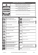
WARNING SYMBOLS AND DEFINITIONS This is the safety alert symbol. It is used to alert you to potential personal injury hazards. Obey all safety messages that follow this symbol to avoid possible injury or death. Indicates a hazardous situation which, if not avoided, will result in death or serious injury. Indicates a hazardous situation which, if not avoided, could result in death or serious injury. Indicates a hazardous situation which, if not avoided, could result in minor or moderate injury.
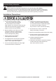
Important Safety Information WARNING! Read all instructions. Failure to follow all instructions may result in fire, serious injury and/or DEATH. The warnings and precautions discussed in this manual cannot cover all possible conditions and situations that may occur. It must be understood by the operator that common sense and caution are factors which cannot be built into this product, but must be supplied by the operator. Installation Precautions 1.
Operation Precautions 1. Do not exceed load capacity. Be aware of dynamic loading! Sudden load movement may briefly create excess load causing product failure. 2. Do not maintain power to the winch if the motor stalls. Verify load is within rated capacity for the wire rope layer, see Specifications on page 2. Make sure the battery is fully charged. Use double line rigging whenever possible, see Double Line Rigging on page 11. 3.
18. Stay alert, watch what you are doing and use common sense when operating. Do not use a winch while you are tired or under the influence of drugs, alcohol or medication. A moment of inattention while operating winches may result in serious personal injury. 28. Do not operate the winch at extreme angles. Do not exceed the angles shown in Figure B for a roller fairlead. For a hawse fairlead, the angle should be as close to straight as possible. 15° 19. Do not overreach.
Service Precautions 1. Wear ANSI-approved safety goggles and heavy-duty leather work gloves during service. 2. Disconnect power to winch and allow it to cool completely before service. 3. Use supplied power cords/wire rope or cables listed in manual only. Do not use thinner/ longer cables or link multiple cables together. 4. Have the winch serviced by a qualified repair person using only identical replacement parts. This will ensure that the safety of the winch is maintained. 5.
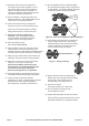
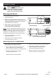
Installation and Setup Read the ENTIRE IMPORTANT SAFETY INFORMATION section at the beginning of this manual including all text under subheadings therein before set up or use of this product. Mounting the Winch 4.72 in. / 120mm 2 in. / 51mm 2. Align the winch perpendicular to center line of the vehicle at the desired location, and mark the locations of the winch base holes. Compare the dimensions of the marked holes to Figure D. 4.72 in. / 120mm 1.
Wiring TO PREVENT SERIOUS INJURY FROM EXPLOSION DUE TO SPARKING AT THE BATTERY CONNECTION: Disconnect the Battery Cables before making other wiring connections. TO PREVENT SERIOUS INJURY FROM LEAKING BATTERY ACID: Do not use a dirty, corroded or leaking battery. Only use a 12V automotive (or equivalent) battery, in good condition. 1. Plan a route for the wiring from the point of the vehicle where the winch will be mounted, or used, to the battery.
Operation Read the ENTIRE IMPORTANT SAFETY INFORMATION section at the beginning of this manual including all text under subheadings therein before set up or use of this product. The instructions that follow are basic guidelines only and cannot cover all situations encountered during use. The operator and assistants must carefully plan usage to prevent accidents. Clutch Operation CAUTION: Do not adjust the clutch unless there is no load on the wire rope. 1.
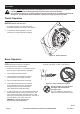
8. Attachment point must be centered in loop of hook and the hook’s safety clasp must be fully closed. See Figure I. Double Line Rigging a. A double line system should be used whenever possible. It reduces the load on the winch, allowing it to work longer with less heat buildup. It reduces load on the winch in two ways: • It utilizes the lower layers of wire rope that have higher capacity, and • It halves the load on the winch through pulley action. Figure I: Correct and incorrect hook attachment 9.
14. Do not operate the winch at extreme angles. Do not exceed the angles shown in Figure B for a roller fairlead. For a hawse fairlead, the angle should be as close to straight as possible. 15° 15° 45° 45° FIGURE B: ROLLER FAIRLEAD MAXIMUM WINCHING ANGLES 15. If the object to be pulled must be pulled at an angle in relation to the winch, use a pulley (sold separately) and an anchor point directly in front of the winch, as shown in Figure C, to keep the Wire Rope pull straight. 16.
Maintenance and Servicing Procedures not specifically explained in this manual must be performed only by a qualified technician. TO PREVENT SERIOUS INJURY FROM ACCIDENTAL OPERATION: Disconnect the Battery Cables before performing any inspection, maintenance, or cleaning procedures. TO PREVENT SERIOUS INJURY FROM WINCH FAILURE: Do not use damaged equipment. If abnormal noise or vibration occurs, have the problem corrected before further use. Cleaning, Maintenance, and Lubrication 1.
Troubleshooting Problem Possible Causes Likely Solutions Motor overheats. 1. Incorrect power cords. 2. Winch running time too long. Motor does not turn on. 1. Switch Assembly not connected properly. 1. Insert Switch Assembly all the way into connector. 2. Tighten nuts on all cable connections. 2. Loose battery cable connections. 3. Fully charge battery. 3. Vehicle battery needs charging. 4. Tap solenoid to loosen contacts. 4. Solenoid malfunctioning. Apply 12 volts to coil terminals directly.
Parts List and Diagram Part 1 2 3 4 5 6 7 8 9 10 11 12 13 14 15 16 17 18 19 Description Screw M6 X 15 Motor Motor Base Nut M8 Brake Screw M4 X 12 O Ring Sliding Bearing Drive Shaft Tie Bar Drum Clip Spline Spring Joint Gear Screw M6 X 10 Clip Gearbox Base Seals Planetary Gear 1 Item 68144 Qty.
Limited 90 Day Warranty Harbor Freight Tools Co. makes every effort to assure that its products meet high quality and durability standards, and warrants to the original purchaser that this product is free from defects in materials and workmanship for the period of 90 days from the date of purchase.