Table of Contents SAFETY Safety ......................................................... 3 Specifications ............................................. 7 Setup .......................................................... 8 Operation ................................................... 11 Maintenance .............................................. 14 Parts List and Diagram .............................. 18 Assembly Diagram .................................... 19 Warranty .....................................
IMPORTANT SAFETY INFORMATION 3. KEEP WORK AREA CLEAN. Cluttered areas and benches invite accidents. 12. SECURE WORK. Use clamps or a vise to hold work when practical. It’s safer than using your hand and it frees both hands to operate tool. 4. DON’T USE IN DANGEROUS ENVIRONMENT. Don’t use power tools in damp or wet locations, or expose them to rain. Keep work area well lighted. 13. DON’T OVERREACH. Keep proper footing and balance at all times. 5. KEEP CHILDREN AWAY.
Grounding Instructions SAFETY TO PREVENT ELECTRIC SHOCK AND DEATH FROM INCORRECT GROUNDING WIRE CONNECTION READ AND FOLLOW THESE INSTRUCTIONS: 110-120 V~ Grounded Tools: Tools with Three Prong Plugs 1. In the event of a malfunction or breakdown, grounding provides a path of least resistance for electric current to reduce the risk of electric shock. This tool is equipped with an electric cord having an equipment-grounding conductor and a grounding plug.
9. As noted previously, Kickback is a sudden reaction to a pinched, bound, or misaligned blade, causing an uncontrolled workpiece to lift up and out of the saw toward the operator. Kickback is usually a result of tool misuse and can be limited or avoided by following the precautions below: • Fence must be completely parallel to the saw blade. • Workpiece must be free from flaws and from foreign objects. 12.
ADDITIONAL TILE SAW SAFETY WARNINGS 24. Industrial applications must follow OSHA guidelines. 19. DO NOT OPERATE WITH ANY GUARD DISABLED, DAMAGED, OR REMOVED. Moving guards must move freely and close instantly. 25. Maintain labels and nameplates on the tool. These carry important safety information. If unreadable or missing, contact Harbor Freight Tools for a replacement. SAFETY 20. The use of accessories or attachments not recommended by the manufacturer may result in a risk of injury to persons. 21.
Vibration Safety 1. Anyone using vibrating tools regularly or for an extended period should first be examined by a doctor and then have regular medical check-ups to ensure medical problems are not being caused or worsened from use. Pregnant women or people who have impaired blood circulation to the hand, past hand injuries, nervous system disorders, diabetes, or Raynaud’s Disease should not use this tool.
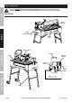
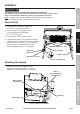
Setup - Before Use: Read the ENTIRE IMPORTANT SAFETY INFORMATION section at the beginning of this manual including all text under subheadings therein before set up or use of this product. SAFETY Functions Miter Gauge Blade (sold separately) SETUP Water Tray Blade Guard Handle OPERATION Table Circuit Breaker Locking Knob Power Switch MAINTENANCE Stand Page 8 For technical questions, please call 1-800-444-3353.
ASSEMBLY SAFETY TO PREVENT SERIOUS INJURY FROM ACCIDENTAL OPERATION: Turn the Power Switch of the tool to its “OFF” position and unplug the tool from its electrical outlet before assembling or making any adjustments to the tool. Note: For additional information regarding the parts listed in the following pages, refer to the Assembly Diagram near the end of this manual. Stand Set Up 1. With assistance, carefully lay the Tile Saw on its side on a flat, level floor surface. 2.
Attaching Locking Knobs 1. Align the Right Guide Rail Stand (111) as shown in Figure 6, right. T-Knob (107) Right Guide Rail Stand (111) SAFETY 2. Remove the shipping screw and attach one Locking Knob (75) through the slot in the Right Guide Rail Stand (111) and into the threaded hole as shown. Note: The Right Guide Rail Stand (111) is held in place by the packaging during shipment. Always tighten the T-Knob (107) to lock the Rail Stand prior to performing maintenance or relocating the Tile Saw. 3.
Operating Instructions Read the ENTIRE IMPORTANT SAFETY INFORMATION section at the beginning of this manual including all text under subheadings therein before set up or use of this product. SAFETY TOOL SET UP TO PREVENT SERIOUS INJURY FROM ACCIDENTAL OPERATION: Turn the Power Switch of the tool to its “OFF” position, remove the key, and unplug the tool from its electrical outlet before assembling or making any adjustments to the tool.
Miter Adjustment 1. Loosen the T-Knob (103A) on the Miter Gauge (102) and position the Miter Gauge at the desired angle. Retighten the T-Knob. SAFETY 2. To adjust the gap between the Miter Gauge (102) and the cutting slot in the Table, loosen the T-Knob (103B) on the Miter Gauge Guide (105). Move the Miter Gauge to the desired position. Retighten the T-Knob.
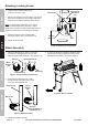
Filling and Draining Water Tray 1. Fill Water Tray (60) before every use with enough clean, cold water to submerge 3/4 of the Water Pump (51). Do not overfill the Tray. Water Pump (51) 3. After draining the water, rinse Tray to remove any sediment. SAFETY Drain Plug (62) 2. To drain the Water Tray (60) place a large bucket under the Drain Plug (62). Remove the Drain Plug located at the bottom of the Water Tray. Once drained, replace the Drain Plug.
Maintenance and Servicing Procedures not specifically explained in this manual must be performed only by a qualified technician. SAFETY TO PREVENT SERIOUS INJURY FROM ACCIDENTAL OPERATION: Turn the Power Switch of the tool to its “OFF” position, remove the key, and unplug the tool from its electrical outlet before performing any inspection, maintenance, or cleaning procedures. TO PREVENT SERIOUS INJURY FROM TOOL FAILURE: Do not use damaged equipment.
Troubleshooting Tool will not start. 1. Cord not connected. 2. No power at outlet. 3. Tool’s circuit breaker tripped. Tool operates slowly. Performance decreases over time. Excessive noise or rattling. Overheating. 4. Internal damage or wear. (Carbon brushes or switch, for example.) Extension cord too long or wire size too small. 1. Blade dull or damaged. 2. Carbon brushes worn or damaged. Internal damage or wear. (Carbon brushes or bearings, for example.) 1. Forcing machine to work too fast. 2.
PLEASE READ THE FOLLOWING CAREFULLY SAFETY THE MANUFACTURER AND/OR DISTRIBUTOR HAS PROVIDED THE PARTS LIST AND ASSEMBLY DIAGRAM IN THIS MANUAL AS A REFERENCE TOOL ONLY. NEITHER THE MANUFACTURER OR DISTRIBUTOR MAKES ANY REPRESENTATION OR WARRANTY OF ANY KIND TO THE BUYER THAT HE OR SHE IS QUALIFIED TO MAKE ANY REPAIRS TO THE PRODUCT, OR THAT HE OR SHE IS QUALIFIED TO REPLACE ANY PARTS OF THE PRODUCT.
Record Product’s Serial Number Here: Note: If product has no serial number, record month and year of purchase instead. MAINTENANCE OPERATION SETUP SAFETY Note: Some parts are listed and shown for illustration purposes only, and are not available individually as replacement parts. Item 60608 For technical questions, please call 1-800-444-3353.
Parts List and Diagram Parts List SAFETY Part SETUP OPERATION 1 2 3 4 5 6 7 8 9 10 11 12 13 14 15 16 17 18 19 20 21 22 23 24 25 26 27 28 29 30 31 32 33 34 35 36 37 38 39 40 41 42 Description Bolt M6 x 30 Spring Washer Flat Washer Sliding Handle Plastic Insert Handle Sleeve Power Cord Cable Sleeve Capacitor Capacitor Clamp Plate Screw Screw Switch Box Cover Switch Box Seal Screw M4 x 10 Flat Washer Circuit Breaker Key Switch Rubber Cable Ring Screw M5 x 14 Flat Washer Motor Switch Box Rubber Pad Motor
Item 60608 44 43 42 For technical questions, please call 1-800-444-3353.
Limited 90 Day Warranty Harbor Freight Tools Co. makes every effort to assure that its products meet high quality and durability standards, and warrants to the original purchaser that this product is free from defects in materials and workmanship for the period of 90 days from the date of purchase.