mini WOODWORKING lathe 95607 Assembly And Operation Instructions Due to continuing improvements, actual product may differ slightly from the product described herein. 3491 Mission Oaks Blvd., Camarillo, CA 93011 Visit our website at: http://www.harborfreight.com To prevent serious injury, read and understand all warnings and instructions before use. To prevent damage to the lathe, see startup and shutdown procedures on page 13 before use. Copyright© 2006 by Harbor Freight Tools®. All rights reserved.
Specifications Motor 110 V~ / 60 Hz / 1 Phase Speed Range 750 - 3200 RPM Drive Spindle Size 3/ Swing Over Bed 8” Distance Between Centers 13” Spindle Bore 7/ Quill Travel 12” Head Stock 4-1/8” H Work Tolerance 0.005” Bed Dimensions 22-3/4” L x 3” W x 5-3/4” H Tailstock Taper MT1 V-belt size 6 x 516 mm Net Weight 46 lb.
. Keep bystanders, children, and visitors away while operating a power tool. Distractions can cause you to lose control. Protect others in the work area from debris such as chips and sparks. Provide barriers or shields as needed. Electrical Safety 1. Grounded tools must be plugged into an outlet properly installed and grounded in accordance with all codes and ordinances. Never remove the grounding prong or modify the plug in any way. Do not use any adapter plugs.
6. Do not overreach. Keep proper footing and balance at all times. Proper footing and balance enables better control of the power tool in unexpected situations. 7. Use safety equipment. Always wear eye protection. Dust mask, nonskid safety shoes, hard hat, or hearing protection must be used for appropriate conditions. Always wear ANSI-approved safety goggles, heavy-duty work gloves, and a dust mask/respirator when using or performing maintenance on this tool. Tool Use And Care 1.
of unauthorized parts or failure to follow maintenance instructions may create a risk of electric shock or injury. SPECIFIC SAFETY RULES 1. Maintain labels and nameplates on the Mini Lathe. These carry important information. If unreadable or missing, contact Harbor Freight Tools for a replacement. 2. Direction of feed. Feed tool into workpiece against the direction of the workpiece only. 3. Avoid unintentional starting. Make sure you are prepared to begin work before turning on the Mini Lathe. 4.
GROUNDING WARNING! Improperly connecting the grounding wire can result in the risk of electric shock. Check with a qualified electrician if you are in doubt as to whether the outlet is properly grounded. Do not modify the power cord plug provided with the tool. Never remove the grounding prong from the plug. Do not use the tool if the power cord or plug is damaged. If damaged, have it repaired by a service facility before use.
2. Double insulated tools may be used in either of the 120 volt outlets shown in the preceding illustration. (See Figure B.) Extension Cords 1. Grounded tools require a three wire extension cord. Double Insulated tools can use either a two or three wire extension cord. 2. As the distance from the supply outlet increases, you must use a heavier gauge extension cord. Using extension cords with inadequately sized wire causes a serious drop in voltage, resulting in loss of power and possible tool damage.
RECOMMENDED MINIMUM WIRE GAUGE FOR EXTENSION CORDS* (120 or 240 VOLT) NAMEPLATE AMPERES EXTENSION CORD LENGTH (at full load) 25 Feet 50 Feet 75 Feet 100 Feet 150 Feet 0 – 2.0 18 18 18 18 16 2.1 – 3.4 18 18 18 16 14 3.5 – 5.0 18 18 16 14 12 5.1 – 7.0 18 16 14 12 12 7.1 – 12.0 18 14 12 10 - 12.1 – 16.0 14 12 10 - - 16.1 – 20.0 12 10 - - - FIGURE C * Based on limiting the line voltage drop to five volts at 150% of the rated amperes.
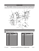
Unpacking When unpacking, make sure the item and its accessories and components are intact and undamaged. If any parts are missing or broken, call Harbor Freight Tools at the number shown on the cover of this manual as soon as possible. See packing list below. P Q C A O R B N L M D K J I F E H V T G U S General Mini Lathe Components Note: Refer to the parts list and diagram at the end of this manual for complete part number listings and locations.
Assembly Instructions Note: For additional information regarding the parts listed in the following pages, refer to the Assembly Diagram near the end of this manual. 1. WARNING! Make sure the Power Switch of the Lathe is in its “OFF” position and that the Lathe is unplugged from its electrical outlet before making any adjustments to the Lathe. 2. Mount the Lathe on a benchtop by first measuring and marking three hole centers. See Figure 1. 3. Drill holes through the marked locations.
Assembly Instructions (continued) The Mini Lathe comes with two different sized Faceplates (A). Use the one best suited to size of the workpiece. Mount the workpiece onto the Faceplate with wood screws (not provided). Make sure the screws are not so long that they enter the workspace of where the material is being removed. Please note: Both Faceplates (A) have an open center. When cutting through a workpiece from the Tailstock (M), the drill bit can go completely through the workpiece.
Assembly Instructions (continued) Installing a spur and center: 1. First, insert the shaft of the Headstock Spur Center (T) into the hollow center of the Headstock Spindle (B). Please see Figure 3. Figure 3 T 2. Then, insert the shaft of the Tailstock Cup Center (Q) into the hollow center of the Tailstock Spindle (N). Please see Figure 4. Figure 4 Q Removing a spur and center: 3.
SPEED CONTROL OPERATION The variable speed control contains the electrical connections to the motor and has three external controls - ON/OFF switch (E), Speed Control Knob (F), and the Circuit Breaker reset button (G). See Figure 6, below. ON/OFF Switch (controls electrical power to the Lathe’s motor) WARNING! Always set the Speed Control Knob (F) to its lowest (counterclockwise) setting before starting the Lathe. Never start a workpiece at maximum speed.
SPEED CONTROL OPERATION Speed Control Knob 1. The Speed Control Knob (F) sets the speed of the Lathe to suit the weight of the workpiece or the type of tool being used. After the Lathe is started, turn the Knob (F) clockwise to increase the Spindle speed (up to maximum of 3200 RPM). See Figure 8. 2. Turn the Knob (F) counterclockwise to decrease the Spindle speed (down to a minimum of 750 RPM). 3. Adjust the Knob (F) until the desired workpiece rotation speed is reached.
Operation Instructions 1. 2. Move the Tailstock (M) by loosening the Lock Lever (R) and pushing the Tailstock to the desired position on the bed. Lock in place by tightening the Lock Lever (R). See Figure 9. The spindle extends up to 2-1/2” from the Tailstock (M) housing. Move the Tailstock Spindle (N) by loosening the Spindle Lock Lever (R) and the Hand Wheel (O). 3. Turn the Hand Wheel (O) clockwise to extend the spindle. Turn the Hand Wheel (O) counterclockwise to retract the spindle.
INSPECTION, MAINTENANCE, AND CLEANING 1. WARNING! Make sure the Power Switch (E) of the Lathe is in its “OFF” position and that the Lathe is unplugged from its electrical outlet before performing any inspection, maintenance, or cleaning procedures. 2. BEFORE EACH USE, inspect the general condition of the Lathe. Check for loose screws, misalignment or binding of moving parts, cracked or broken parts, damaged electrical wiring, and any other condition that may affect its safe operation.
PARTS LIST Part Q’ty Part 1 Bed Description 1 29 Spec label Description Q’ty 1 2 Retaining plate 1 30 Set screw M6x10 1 3 PHLP HD screw M5x8 2 31 Drive pulley 1 4 Special set screw M6x8 1 32 Belt K-516 1 5 Hand wheel 1 33 Set screw M6x10 1 6 Tailstock 1 34 Motor pulley 1 7 T-lock knob bolt for tailstock 1 35 Power cord 1 8 Cap screw M8x40 2 36 Variable speed box 1 9 Sleeve 1 37 PHLP HD screw M4x8 4 10 Eccentric axis 1 38 Cap screw M8x25 1 11
ASSEMBLY DIAGRAM SKU 95607 For technical questions, please call 1-800-444-3353.
Wiring DIAGRAM SKU 95607 For technical questions, please call 1-800-444-3353.
LIMITED 90 DAY WARRANTY Harbor Freight Tools Co. makes every effort to assure that its products meet high quality and durability standards, and warrants to the original purchaser that this product is free from defects in materials and workmanship for the period of 90 days from the date of purchase.