® FLOOR STAPLER WITH HAMMER AND CASE Model 90399 ASSEMBLY and OPERATING INSTRUCTIONS ® 3491 Mission Oaks Blvd., Camarillo, CA 93011 Visit our Web site at http://www.harborfreight.com Copyright© 2003 by Harbor Freight Tools®. All rights reserved. No portion of this manual or any artwork contained herein may be reproduced in any shape or form without the express written consent of Harbor Freight Tools.
Specifications Air Inlet 1/4” - 18 NPT Recommended Air Pressure 70-90 PSI Maximum Air Pressure 100 PSI Dimensions 22-1/2” x 17-1/2” x 3-1/8” Weight 21.85 Lbs. Magazine Capacity 80 Pcs. / Top Loaded Air Consumption 5.0 CFM @ 80 PSI Fastener Size Range 3/4” to 2” Long x 15 Gauge Staples included: 400, 1/2” crown, 2” Long, 15 Gauge Iincludeds: Tool Oil, 3 Hex Wrenches, Storage Case, Hammer Note: SKU 90429 - 2”, 15 Gauge Staples are available from Harbor Freight Tools.
7. Dress properly. Do not wear loose clothing or jewelry as they can be caught in moving parts. Protective, electrically nonconductive clothes and nonskid footwear are recommended when working. Wear restrictive hair covering to contain long hair. 8. Use eye and ear protection. Always wear ANSI approved impact safety goggles. Wear a full face shield if you are producing metal filings or wood chips. Wear an ANSI approved dust mask or respirator when working around metal, wood, and chemical dusts and mists.
21. Compressed air only. Never use combustible gases as a power source. Warning: The warnings, cautions, and instructions discussed in this instruction manual cannot cover all possible conditions and situations that may occur. It must be understood by the operator that common sense and caution are factors which cannot be built into this product, but must be supplied by the operator.
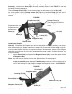
Operation (continued) Assembly - Attaching the Arm (48) is the only assembly required. See FIGURE 1 and the Assembly Drawing on page 8. The two Clamp Screws (44) fit in the recessed gaps on the lower part of the Arm (48). As shown below, hold the Clamp Screws (44) in place around the Body (18) and add a Washer (45) and a Nut (46) to the threaded ends of the Clamp Screws (44). Tighten them securely. FIGURE 1 Clamp Screws (44) Staples exit the Stapler from the bottom of the Shoe (28).
Operation (continued) Using the Floor Stapler THIS TOOL DOES NOT USE A SAFETY MECHANISM; extreme caution must be used whenever this tool is connected to an air supply. If the tool is dropped or if the Hammer Face (10) is accidentally struck, then the tool will fire a staple, potentially causing SEVERE PERSONAL INJURY. 1. Connect the Floor Stapler to the air hose and turn on the FIGURE 3 air compressor. Note: Before using on a floor, test the unit on a scrap piece of wood.
Anytime any maintenance or repairs are done (including clearing jams), FIRST: 1. 2. 3. 4. Disconnect the Stapler from the air hose. Empty Magazine (30a) completely. Attempt to fire the Stapler into a piece of scrap wood to ensure that it is disconnected and is incapable of firing any staples. Always leave Magazine Cover (33a) open during maintenance. The Magazine is spring-loaded and may cause parts or a staple to fly out of the Stapler. Clearing Jams 1. 2. 3. 5. 6. 7. 8. 9. 10. 11.
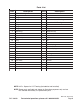
Parts List Part Description Part Description 1 Cylinder Bushing 24 Washer 2 Plunger 25 Screw 3 0-ring 26 Screw 4 0-ring 27 Spacer for 25/32" Flooring 5 Poppet 27a Spacer for 1/2" Flooring 6 0-ring 28 Shoe 7 0-ring 29a Pin 8 0-ring 30a Magazine 9 Piston Assy.
Assembly Diagram #27 - Installed: (Spacer for 25/32” Flooring) #27a - Spacer is included with tool, not installed (Spacer for 1/2” Flooring) REV 04/05; 02/06 SKU 90399 For technical questions, please call 1-800-444-3353.