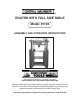
ROUTER WITH FULL SIZE TABLE Model 91130 ASSEMBLY AND OPERATING INSTRUCTIONS ® 3491 Mission Oaks Blvd., Camarillo, CA 93011 Visit our Web site at: http://www.harborfreight.com Copyright© 2004 by Harbor Freight Tools®. All rights reserved. No portion of this manual or any artwork contained herein may be reproduced in any shape or form without the express written consent of Harbor Freight Tools. For technical questions or replacement parts, please call 1-800-444-3353.
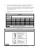
PRODUCT SPECIFICATIONS Item Electrical Requirements Table Dimensions Table Height Overall Height Cutting Depth Collet Capacity Accessories Weight Description 120V / 60 Hz / 750 Watts / 4.3 Load Amps 1 HP Motor / 8,400-27,800 RPM Variable Speed 3- Prong, Grounded, Power Plug 27” Wide x 18” Deep x 1-1/2” Thick 38” 43-1/2” 1-27/64” 1/4” And 1/2” 1/4” Collet / 1/2” Collet / Miter Gauge Guide Fence / Feather Board / Wrench Dust Collector Port 75.
. Keep bystanders, children, and visitors away while operating a power tool. Distractions can cause you to lose control. Protect others in the work area from debris such as chips and sparks. Provide barriers or shields as needed. ELECTRICAL SAFETY 4. Grounded tools must be plugged into an outlet properly installed and grounded in accordance with all codes and ordinances. Never remove the grounding prong or modify the plug in any way. Do not use any adapter plugs.
11. Dress properly. Do not wear loose clothing or jewelry. Contain long hair. Keep your hair, clothing, and gloves away from moving parts. Loose clothes, jewelry, or long hair can be caught in moving parts. 12. Avoid accidental starting. Be sure the Power Switch is off before plugging in. Carrying power tools with your finger on the Power Switch, or plugging in power tools with the Power Switch on, invites accidents. 13. Remove adjusting keys or wrenches before turning the power tool on.
22. Check for misalignment or binding of moving parts, breakage of parts, and any other condition that may affect the tool’s operation. If damaged, have the tool serviced before using. Many accidents are caused by poorly maintained tools. 23. Use only accessories that are recommended by the manufacturer for your model. Accessories that may be suitable for one tool may become hazardous when used on another tool. SERVICE 24. Tool service must be performed only by qualified repair personnel.
7. Make sure the Power Switch is in the “OFF” position before plugging in the Power Cord. 8. Do not use this Router for cutting metals or brittle materials. Do not cut dangerous materials, such as asbestos which can cause harmful dust or vapors. 9. Before using the Router, make sure the router bit (not included) is properly mounted. Make sure the router bit is not bent or cracked. 10. Allow the router bit to spin up to full speed before feeding wood into it.
21. Maintain this product with care. Keep the Router clean and dry for better and safer performance. Make sure to keep router bits sharp and clean. For your safety, service and maintenance should be performed regularly by a qualified technician. 22. Use the right tool or attachment for the right job. Do not attempt to force a small tool or attachment to do the work of a larger industrial tool or attachment. There are certain applications for which this product was designed.
GROUNDING WARNING! Improperly connecting the grounding wire can result in the risk of electric shock. Check with a qualified electrician if you are in doubt as to whether the outlet is properly grounded. Do not modify the power cord plug provided with the tool. Never remove the grounding prong from the plug. Do not use the tool if the power cord or plug is damaged. If damaged, have it repaired by a service facility before use.
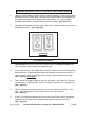
DOUBLE INSULATED TOOLS: TOOLS WITH TWO PRONG PLUGS 4. Tools marked “Double Insulated” do not require grounding. They have a special double insulation system which satisfies OSHA requirements and complies with the applicable standards of Underwriters Laboratories, Inc., the Canadian Standard Association, and the National Electrical Code. (See Figure B.) 5. Double insulated tools may be used in either of the 120 volt outlets shown in the following illustration. (See Figure B.) FIGURE B EXTENSION CORDS 1.
6. If you are using an extension cord outdoors, make sure it is marked with the suffix “W-A” (“W” in Canada) to indicate it is acceptable for outdoor use. 7. Make sure your extension cord is properly wired and in good electrical condition. Always replace a damaged extension cord or have it repaired by a qualified electrician before using it. 8. Protect your extension cords from sharp objects, excessive heat, and damp or wet areas.
PRODUCT FEATURES Part # 8B 9B 10B 14B 20B 21B 28B 2C 8C 13C Description Key Power Switch (not shown) Safety Cover Large Lock Knob Main Table Feather Board Variable Speed Adjustment Lower Fence Fence Lock Knob Fence Adjusting Knob (13C) (24C) Part # 14C 16C 24C 26C 27C 14D 15D 19D 23D 22E (26C) Description Feather Board Upper Fence Dust Port Box Dust Port Miter Gauge Height Adjusting Ring Collet Assembly Cover Collet Nut Height Adjusting Lock Spindle Lock Lever (14C) (16C) (2C) (8C) (8C) (21B) (27C
ASSEMBLY INSTRUCTIONS NOTE: For additional references to the parts listed in the following pages, refer to the Assembly Diagrams on pages 28, 29, 30, 31, and 32. To Assemble The Base: 1. Place one Table (8A) upside down on a level floor surface. Attach a Support Board 1 (2A) to opposite corners of the Table, and attach a Support Board 2 (1A) to the two remaining opposite corners of the Table using Screws (3A), Washers (6A), and Plastic Nuts (7A). Repeat this procedure for the remaining two Tables (8A).
3. With assistance, turn the assembled Base right side up. (See Figure F.) 4. With assistance, move the assembled Base to the floor surface where the Router will be used. NOTE: Make sure the floor surface is dry, flat, level, and sturdy enough to support the weight of the Router, workpieces, and any additional tools and equipment. Use the four Support Legs 2 (9A) as a template to mark four places where mounting holes will be drilled in the floor surface. Then, temporarily set the assembled Base aside.
To Attach The Mid-Section To The Body: 1. With assistance, place the Mid-Section of the Router Table on top of the Base. (See Figure H.) 2. Align the two mounting holes at the bottom of each Support Leg (12B) with the two mounting holes at each end of the Table (8A). (See Figure H.) 3. Insert a Square Head Screw (11B) upward through each of the two mounting holes at both ends of the Table (8A) and through the two mounting holes in each Support Leg (12B).
LEFT SIDE BOARD (17B) SCREW (15B) WASHER (16B) PLASTIC LOCK NUT (18B) POWER SWITCH (9B) VARIABLE SPEED ADJUSTMENT (28B) FIGURE I mounting holes in the Corner Washers and Support Legs. (See Figure J.) 3. Insert eight Square Head Bolts (22B) downward through the eight mounting holes in the Main Table (20B) and through the eight mounting holes in the Corner Washers (19B) and Support Legs (12B). Then secure the Main Table to the Support Legs, using Large Washers (13B) and Plastic Lock Nuts (18B).
4. Screw a Nut (24B) downward on each of the eight Hex Screws (23B). Insert the Hex Screws downward through the eight mounting holes located on the Main Table (20B). Make sure the Nuts are above the mounting holes. Then, screw a Nut (24B) upward on each of the eight Hex Screws to secure the Hex Screws to the Main Table. (See Figure J.) To Attach The Motor Assembly: 1. Lower the Adjustment Board (17D) with its pre-attached Motor Assembly through the top of the Main Table (20B).
2. Position the Upper Fence (16C) on the Main Table (20B). 3. Use two Screws (9C) to attach a Fence Support (10C) to the back of the Upper Fence (16C), making sure to use two of the outermost pre-fitted Nuts (11C) in the channel of the Upper Fence. Do not tighten yet. Repeat this procedure for the remaining Fence Support (See Assembly Diagram C.) 4.
rear of the Upper Fence (16C), using the remaining two pre-fitted Nuts (11C) in the channel of the Upper Fence and two Screws (9C). (See Assembly Diagram C and Figure M.) PROTECTOR (23C) UPPER FENCE (16C) DUST PORT ASSY. (26C) FENCE LOCK KNOB (8C) FIGURE M To Install And Remove Collets: 1. WARNING! Always make sure the Power Switch (9B) is in its “OFF” position and the Power Cord/Plug (1B) is unplugged from its electrical outlet before making any adjustments to the Router Table. 2.
WRENCH (21D) COLLET ASSEMBLY COVER (15D) HEIGHT ADJUSTMENT LOCK (23D) HEIGHT ADJUSTING RING (14D) COLLET NUT (19D) COLLET NUT (19D) WRENCH (21D) FIGURE N 7. Use the Wrench (21D) to turn the Collet Nut (19D) in a counterclockwise direction while pulling and holding the Spindle Lock Lever (22E) forward. Then, remove the Collet Nut. (See Figures K and N.) 8.
9. Make sure to insert the shaft of the router bit all the way into the Collet (18D, 24D). (See Figure P.) 10. Tighten the Collet Nut (19D) by pulling and holding the Spindle Lock Lever (22E) forward while screwing the Collet Nut in a clockwise direction. (See Figures K and P.) ROUTER BIT (NOT INCLUDED) ROUTER BIT COLLET NUT (19D) FIGURE P 11. Replace the Collet Assembly Cover (15D). (See Figure N.) 12. Adjust the depth of cut to the desired depth by turning the Height Adjustment Ring (14D).
2. Fit the Adjustment Tool (27D) in the corresponding slots of the Height Adjusting Ring (14D) and turn the Ring in a clockwise direction for a deeper depth of cut or counterclockwise for a lesser depth of cut. (See Figure Q.) 3. NOTE: The Height Adjustment Ring (14D) is marked with a straight arrow pointing to the edge of the Adjustment Board (17D). The Adjustment Board (17D) is marked with ten corresponding lines.
2. Attach the second Feather Board (21B) horizontally to the Main Table (20B). To do so, insert two Square Head Screws (11B) upward through the Feather Board. Then slide the head of both Screws into the keyhole slot located in the channel used for the Miter Gauge (27C). Secure the Feather Board to the Main Table, using two Large Washers (13B) and two Large Lock Knobs (14B). (See Figure S.
4. NOTE: For more convenience when making miter cuts, the Upper Fence (16C) may be moved to its furthest position away from the router bit. (See Figure T.) MAIN TABLE (20B) MITER GAUGE CHANNEL FENCE ADJUSTING KNOB (13C) UPPER FENCE (16C) MITER GAUGE (27C) FENCE LOCK KNOB (8C) FIGURE T To Adjust The Upper Fence: 1. The Upper Fence (16C) can be adjusted according to the size of the workpiece and the application being performed. To do so, loosen the four Fence Adjusting Knobs (13C). (See Figure T.) 2.
SAFETY COVER (10B) VARIABLE SPEED ADJ. (28B) KEY (8B) POWER SWITCH (9B) FIGURE U To Turn On The Router Table: 1. Connect the Power Cord/Plug (1B) to the nearest grounded, 120 volt, electrical outlet. 2. Depress the Key (8B), and lift up on the Safety Cover (10B). Then, depress the Power Switch (9B) to its “ON” position. (See Figure U.) 3. To turn off the Router Table, simply depress the Safety Cover (10B) to snap it shut.
5. Feed the workpiece gradually from right to left against the rotation of the cutter. Keep the feed rate constant. Feeding the workpiece too quickly will slow the Motor of the machine. Feeding the workpiece too slowly will cause burns to the workpiece. 6. On very hard wood or large cuts it may be necessary to make more than one pass at progressive depth settings until the desired depth of cut is made. 7. When finished, depress the Safety Cover (10B) to turn off the Router Table.
PARTS LIST A Part # 1A 2A 3A 4A 5A Description Support Board 2 Support Board 1 Screw (M5 x 12) Support Leg 1 Leg Washer Qty. 2 2 60 4 4 Part # 6A 7A 8A 9A Description Washer (5) Plastic Lock Nut (M5) Table Support Leg 2 Qty. 60 60 3 4 PARTS LIST B Part # 1B 2B 3B 4B 5B 6B 7B 8B 9B 10B 11B 12B 13B 14B 15B 16B 17B Description Power Cord & Plug Cord Clip Cord Protector Switch Box Base Plastic Nail Locking Buckle Plastic Screw (2.
PARTS LIST D Part # 1D 2D 3D 4D 5D 6D 7D 8D 9D 10D 11D 12D 13D 14D Description Screw (M4 x 10) Plastic Lock Nut Washer (4) End Running Knot Slip Knot Snail Knot Block Ring (45) Large Spring Slip Groove Turning Piece Steel Bead (5) Locking Piece Partial Axis Height Adjusting Ring Qty. 10 4 4 1 1 1 1 1 1 1 6 1 1 1 Part # 15D 16D 17D 18D 19D 20D 21D 22D 23D 24D 25D 26D 27D 28D 29D Description Collet Assy. Cover Screw (M4 x 12) Adjustment Board Collet (1/2”) Collet Nut C-Ring Wrench Small Spring Height Adj.
SKU 91130 For technical questions, please call 1-800-444-3353. 7A 6A 8A 9A NOTE: Some parts are listed and shown for illustration purposes only, and are not available individually as replacement parts.
SKU 91130 For technical questions, please call 1-800-444-3353. 10B 24B 23B 24B 27B 26B 18B 13B 31B 24B 33B 13B 18B 25B 9B 8B 7B 6B 5B4B 3B 2B 1B 22B 32B 28B 29B 30B 31B NOTE: Some parts are listed and shown for illustration purposes only, and are not available individually as replacement parts.
SKU 91130 3C 2C 1C 6C 7C 8C For technical questions, please call 1-800-444-3353. 4C 26C 7C 13C 25C 24C 9C 23C 18C 17C 16C 15C 7C 8C 19C 20C 22C 21C NOTE: Some parts are listed and shown for illustration purposes only, and are not available individually as replacement parts. 27: MITER GAUGE NOT SHOWN.
SKU 91130 For technical questions, please call 1-800-444-3353. 29D 18D 22D 1D 23D 1D 15D 14D 13D 12D 11D 10D 9D 8D 7D 6D 4D 20D 19D 5D 25D 28D 26D 3D 2D 24D 1D NOTE: Some parts are listed and shown for illustration purposes only, and are not available individually as replacement parts.
SKU 91130 For technical questions, please call 1-800-444-3353. 4E 13E 12E 22E 10E 36E 11E 23E 9E 24E 8E 25E 7E 31E 26E 27E 6E 5E 32E 4E 3E 2E 28E 1E 30E 29E NOTE: Some parts are listed and shown for illustration purposes only, and are available individually as replacement parts.