2.5 HP CHIPPER/SHREDDER Model 92281 ASSEMBLY AND OPERATING INSTRUCTIONS ® 3491 Mission Oaks Blvd., Camarillo, CA 93011 Visit our Web site at: http://www.harborfreight.com TO PREVENT SERIOUS INJURY, READ AND UNDERSTAND ALL WARNINGS AND INSTRUCTIONS BEFORE USE. © Copyright 2004 by Harbor Freight Tools®. All rights reserved. No portion of this manual or any artwork contained herein may be reproduced in any shape or form without the express written consent of Harbor Freight Tools.
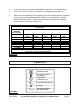
PRODUCT SPECIFICATIONS Item Description Electrical Requirements Chipper/Shredder Capacity Blade Quantity/Type Discharge Chute Size Opening Size Wheel Size Accessories Wrenches Included Overall Dimensions Weight 115 V / 60 Hz / 2000 Watt 4.15 AMPs (No Load) / 5.20 AMPs (With Load) 2.
WORK AREA 1. Keep your work area clean and well lit. Cluttered and dark work areas invite accidents. 2. Do not operate power tools in explosive atmospheres, such as in the presence of flammable liquids, gases, or dust. Power tools create sparks which may ignite the dust or fumes. 3. Keep bystanders, children, and visitors away while operating a power tool. Distractions can cause you to lose control. ELECTRICAL SAFETY 1.
2. Dress properly. Do not wear loose clothing or jewelry. Contain long hair. Keep your hair, clothing, and gloves away from moving parts. Loose clothes, jewelry, or long hair can be caught in moving parts. 3. Avoid accidental starting. Be sure the Power Switch is off before plugging in. Plugging in power tools with the Power Switch on invites accidents. 4. Remove adjusting keys or wrenches before turning the power tool on.
any other condition that may affect the tool’s operation. If damaged, have the tool serviced before using. Many accidents are caused by poorly maintained tools. 7. Use only accessories that are recommended by the manufacturer for your model. Accessories that may be suitable for one tool may become hazardous when used on another tool. SERVICE 1. Tool service must be performed only by qualified repair personnel. Service or maintenance performed by unqualified personnel could result in a risk of injury. 2.
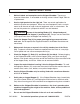
2. The grounding prong in the plug is connected through the green wire inside the cord to the grounding system in the tool. The green wire in the cord must be the only wire connected to the tool’s grounding system and must never be attached to an electrically “live” terminal. (See Figure A.) 3. Your tool must be plugged into an appropriate outlet, properly installed and grounded in accordance with all codes and ordinances. The plug and outlet should look like that in the following illustration.
6. If you are using an extension cord outdoors, make sure it is marked with the suffix “W-A” (“W” in Canada) to indicate it is acceptable for outdoor use. 7. Make sure your extension cord is properly wired and in good electrical condition. Always replace a damaged extension cord or have it repaired by a qualified electrician before using it. Protect your extension cords from sharp objects, excessive heat, and damp or wet areas.
SPECIFIC SAFETY RULES 1. Maintain labels and nameplates on the Chipper/Shredder. These carry important information. If unreadable or missing, contact Harbor Freight Tools for a replacement. 2. Use the right product for the right job. There are certain applications for which this product was designed. Do not use small equipment, tools, or attachments to do the work of larger industrial equipment, tools, or attachments. Do not use this product for a purpose for which it was not intended. 3.
12. Keep all electrical connections dry and off the ground. 13. Do not handle the Power Switch (47) with wet hands. 14. Never leave the Chipper/Shredder unattended when it is plugged into an electrical outlet. Turn off the machine, and unplug it from its electrical outlet. 15. Allow the Blades (15) to spin up to full speed before feeding limbs into them. When turning off the Chipper/Shredder, allow the Blades to spin down and stop on their own.
25. WARNING! To avoid personal injury or death, NEVER attempt to alter or disable the Safety Shut-Off Switch (42). 26. WARNING! Some dust created by power sanding, sawing, grinding, drilling, and other construction activities, contain chemicals known (to the State of California) to cause cancer, birth defects or other reproductive harm.
ASSEMBLY INSTRUCTIONS NOTE: For additional information regarding the parts listed in the following pages, refer to the Assembly Diagram on page 17. WARNING! Always make sure the Power Switch (47) of the Chipper/Shredder is in its “OFF” position and the unit is unplugged from its electrical outlet prior to assembling the unit, unclogging the unit, or making any adjustments to the unit. The Body (13) is pre-attached to the Motor Support (26) by the manufacturer, and requires no additional assembly.
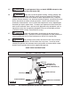
2. Attach the Left Support Leg (61) to the left side of the Motor Support (26), using two Screws (27), two Washers (34), and two Lock Nuts (33). (See Figure F.) 3. Attach the Right Support Leg (35)) to the right side of the Motor Support (26), using two Screws (27), two Washers (34), and two Lock Nuts (33). (See Figure F.
OPERATING INSTRUCTIONS 1. WARNING! Use safety equipment. Always wear ANSI approved safety impact glasses under an ANSI approved full face shield, ANSI approved hearing and breathing protection, heavy duty work gloves, and nonskid safety shoes and work pants and work shirt. 2. Make sure to position the Chipper/Shredder on a flat, level, dry ground surface. Position the machine so that the Chute (32) is pointed in a safe direction, at least 25 feet from any people, animals, or objects.
and turn the Power Switch to its “ON” position to resume cutting. NEVER attempt to disable the Circuit Breaker. (See Figure H.) 11. NOTE: The Motor is equipped with a Safety Shut-Off Switch (42) located on the top portion of the Motor Support (26). Should the Motor not restart, check to make sure the Body (13) is firmly secured to the Motor Support. If necessary, retighten the Knob (7) to ensure a solid connection between the Body and Motor Support. (See Figure E.) 12.
INSPECTION, MAINTENANCE, AND CLEANING 1. WARNING! Make sure the Power Switch (47) of the Chipper/Shredder is in its “OFF” position and that the machine is unplugged from its electrical outlet before performing any inspection, maintenance, or cleaning procedures. 2. Before each use, inspect the general condition of the Chipper/Shredder. Check for loose screws, misalignment or binding of moving parts, damaged electrical wiring, jammed Blades (15), and any other condition that may affect its safe operation.
PLEASE READ THE FOLLOWING CAREFULLY THE MANUFACTURER AND/OR DISTRIBUTOR HAS PROVIDED THE PARTS LIST AND ASSEMBLY DIAGRAM IN THIS MANUAL AS A REFERENCE TOOL ONLY. NEITHER THE MANUFACTURER OR DISTRIBUTOR MAKES ANY REPRESENTATION OR WARRANTY OF ANY KIND TO THE BUYER THAT HE OR SHE IS QUALIFIED TO MAKE ANY REPAIRS TO THE PRODUCT, OR THAT HE OR SHE IS QUALIFIED TO REPLACE ANY PARTS OF THE PRODUCT.
69: 5MM ALLEN WRENCH NOT SHOWN. 70: 6MM ALLEN WRENCH NOT SHOWN. 71: 13MM DOUBLE END WRENCH NOT SHOWN. 72: 16MM DOUBLE END WRENCH NOT SHOWN. ASSEMBLY DIAGRAM NOTE: Some parts are listed and shown for illustration purposes only, and are not available individually as replacement parts. SKU 92281 For technical questions, please call 1-800-444-3353.
WIRING DIAGRAM SKU 92281 For technical questions, please call 1-800-444-3353.