3″ MINI TOOL GRINDER 94071 SET UP AND OPERATING INSTRUCTIONS Visit our website at: http://www.harborfreight.com Read this material before using this product. Failure to do so can result in serious injury. SAVE THIS MANUAL. Copyright© 2005 by Harbor Freight Tools®. All rights reserved. No portion of this manual or any artwork contained herein may be reproduced in any shape or form without the express written consent of Harbor Freight Tools. Diagrams within this manual may not be drawn proportionally.
CONTENTS IMPORTANT SAFETY INFORMATION............................ 3 GENERAL TOOL SAFETY WARNINGS...................................... 3 GROUNDING INSTRUCTIONS..... 5 110-120 V~ GROUNDED TOOLS: TOOLS WITH THREE PRONG PLUGS............................................. 5 GRINDER SAFETY WARNINGS........ 6 SPECIFICATIONS.......................... 8 UNPACKING.................................. 8 ASSEMBLY INSTRUCTIONS........ 8 TO ATTACH THE RIGHT MOVABLE TOOL REST:.................
CAUTION, used with the safety alert symbol, indicates a hazardous situation which, if not avoided, could result in minor or moderate injury. SAVE THIS MANUAL Keep this manual for the safety warnings and precautions, assembly, operating, inspection, maintenance and cleaning procedures. Write the product’s serial number in the back of the manual near the assembly diagram (or month and year of purchase if product has no number). Keep this manual and the receipt in a safe and dry place for future reference.
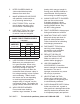
5. KEEP CHILDREN AWAY. All visitors should be kept safe distance from work area. 6. MAKE WORKSHOP KID PROOF with padlocks, master switches, or by removing starter keys. 7. DON’T FORCE TOOL. It will do the job better and safer at the rate for which it was designed. 8. USE RIGHT TOOL. Don’t force tool or attachment to do a job for which it was not designed. (120 VOLT) (at full load) EXTENSION CORD LENGTH 25’ 50’ 100’ 150’ 0–6 18 16 16 14 6.1 – 10 18 16 14 12 10.
its intended function – check for alignment of moving parts, binding of moving parts, breakage of parts, mounting, and any other conditions that may affect its operation. A guard or other part that is damaged should be properly repaired or replaced. 19. DIRECTION OF FEED. Feed work into a blade or cutter against the direction of rotation of the blade or cutter only. 20. NEVER LEAVE TOOL RUNNING UNATTENDED. TURN POWER OFF. 3.
9. The outlet must be properly installed and grounded in accordance with all codes and ordinances. 13. When servicing use only identical replacement parts. 1. Wear eye protection. 14. Only use safety equipment that has been approved by an appropriate standards agency. Unapproved safety equipment may not provide adequate protection. Eye protection must be ANSI-approved and breathing protection must be NIOSH-approved for the specific hazards in the work area. 2.
varies, depending on how often you do this type of work. To reduce your exposure to these chemicals: work in a well ventilated area, and work with approved safety equipment, such as those dust masks that are specially designed to filter out microscopic particles. (California Health & Safety Code § 25249.5, et seq.) 20. WARNING: Handling the cord on this product will expose you to lead, a chemical known to the State of California to cause cancer, and birth defects or other reproductive harm.
SPECIFICATIONS ASSEMBLY INSTRUCTIONS Electrical Input 120 V~ / 1 A (Start) Arbor Shaft 1/ ″ 2 No Load Speed 3450 RPM Mounting Holes 3/16″ Diameter WARNING! Turn the Grinder off and unplug it before assembly. To Attach The Right Movable Tool Rest: 1. The left Movable Tool Rest has been pre-attached by the manufacturer. However, the right Movable Tool Rest must be attached by the operator prior to using the Grinder. (See Figure E.) 2.
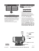
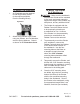
To Attach The Eyeshield: 1. To Mount The Grinder On A Workbench: An Eyeshield must be attached to both Right Safety Guard (to be used as protection from the Grinding Wheel). CAUTION! Make sure the workbench on which the Grinder will be mounted is flat, level, and sturdy enough to support the weight of the Grinder, any workpieces, and any additional tools. Eyeshield 2. Attach the Eyeshield to the Guard using two Screws, two Flat Washers, and two Spring Washers.
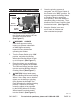
OPERATING INSTRUCTIONS FIGURE F 6. Once the grinding process is competed, turn the Power Switch of the Grinder to its “OFF” position. Do not press against the Buffing Wheel or Grinding Wheel to stop them from spinning. Allow the Wheels to completely stop on their own. Then, disconnect the Power Cord/Plug from its electrical outlet. (See Figure F.) 7. Keep the Grinder in an area out of reach of children and other unauthorized people.
INSPECTION, MAINTENANCE, AND CLEANING 1. WARNING! Turn the Grinder’s Power Switch to its “OFF” position and unplug the tool from its electrical outlet before performing any inspection, maintenance, or cleaning. 2. Before each use: Inspect the general condition of the Grinder. Check for misalignment or binding of moving parts, loose, cracked or broken parts, damaged Power Cord, and any other condition that may affect its safe operation.
PLEASE READ THE FOLLOWING CAREFULLY THE MANUFACTURER AND/OR DISTRIBUTOR HAS PROVIDED THE PARTS LIST AND ASSEMBLY DIAGRAM IN THIS MANUAL AS A REFERENCE TOOL ONLY. NEITHER THE MANUFACTURER OR DISTRIBUTOR MAKES ANY REPRESENTATION OR WARRANTY OF ANY KIND TO THE BUYER THAT HE OR SHE IS QUALIFIED TO MAKE ANY REPAIRS TO THE PRODUCT, OR THAT HE OR SHE IS QUALIFIED TO REPLACE ANY PARTS OF THE PRODUCT.
ASSEMBLY DIAGRAM REV 11a SKU 94071 For technical questions, please call 1-800-444-3353 PAGE 13
LIMITED 90 DAY WARRANTY Harbor Freight Tools Co. makes every effort to assure that its products meet high quality and durability standards, and warrants to the original purchaser that this product is free from defects in materials and workmanship for the period of 90 days from the date of purchase.