INDUSTRIAL BLAST CABINET WITH DUAL DOORS Model 94274 ASSEMBLY AND OPERATING INSTRUCTIONS Diagrams within this manual may not be drawn proportionally. Due to continuing improvements, actual product may differ slightly from the product described herein. Distributed exclusively by Harbor Freight Tools®. 3491 Mission Oaks Blvd., Camarillo, CA 93011 Visit our website at: http://www.harborfreight.com Read this material before using this product. Failure to do so can result in serious injury.
PRODUCT SPECIFICATIONS Electrical Requirements 120 VAC / 60 Hz / 40 Watts (Cabinet) 110 VAC / 60 Hz / 12.0 AMPs (Vacuum Motor) Power Cord Type: 18 AWG x 3C SJT x 76” Long Power Plug Type: 3-Prong, Grounded Fluorescent Light Type: 18 Watt, 23” L x 1” Diameter (Qty. 2) Working Pressure 50 ~ 125 PSI Pressure Gauge Scale 0 ~ 150 PSI: Numbered @ 30 PSI Increments / Marked @ 5 PSI Increments 0 ~ 1 MPa: Numbered @ 0.2 MPa Increments / Marked @ 0.
2. Keep bystanders, children, and visitors away while operating a power tool. Distractions can cause you to lose control. Protect others in the work area from debris such as chips and sparks. Provide barriers or shields as needed. PERSONAL SAFETY 1. Stay alert. Watch what you are doing, and use common sense when operating a power tool. Do not use a power tool while tired or under the influence of drugs, alcohol, or medication.
5. Check for misalignment or binding of moving parts, breakage of parts, and any other condition that may affect the tool’s operation. If damaged, have the tool serviced before using. Many accidents are caused by poorly maintained tools. 6. Use only accessories that are recommended by the manufacturer for your model. Accessories that may be suitable for one tool may become hazardous when used on another tool. SERVICE 1. Tool service must be performed only by qualified repair personnel.
8. Disconnect air hose and release any built-up air pressure. Never service the Blast Cabinet or disassemble with the air hose attached. Always release any built-up air even after disconnecting hose. Disconnect the Blast Cabinet when not in use. 9. Stay alert. Watch what you are doing. Use common sense. Do not operate any tool or equipment when you are tired. 10. Check for damaged parts.
20. Whenever possible, perform an abrasive blasting test on a small area of the object to be blasted. If necessary, adjust the distance to the object and/or change the Nozzle of the Blast Gun for more effective results. 21. Make sure to read and understand all safety warnings and precautions as outlined in the manufacturer’s manual for the object you intend to blast with abrasives. 22. Avoid unintentional starting.
10. Report all cases of silicosis to State health departments and to OSHA or the Mine Safety and Health Administration (MSHA). 24. Before each use, check the seal on all doors of the Blast Cabinet. Only operate the Blast Cabinet with all doors securely closed. 25. WARNING! This product, when used for abrasive blasting and similar applications, produces chemicals known to the State of California to cause cancer and birth defects (or other reproductive harm).
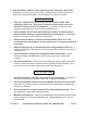
REGULATOR AIR COMPRESSOR TO BLAST CABINET IN-LINE FILTER FIGURE A SAVE THESE INSTRUCTIONS GROUNDING WARNING! Improperly connecting the grounding wire can result in the risk of electric shock. Check with a qualified electrician if you are in doubt as to whether the outlet is properly grounded. Do not modify the power cord plug provided with the tool. Never remove the grounding prong from the plug. Do not use the tool if the power cord or plug is damaged.
3. Your tool must be plugged into an appropriate outlet, properly installed and grounded in accordance with all codes and ordinances. The plug and outlet should look like those in the following illustration. (See Figure B.) THIS PRODUCT USES A 3-PRONG, GROUNDED PLUG 120 VOLT, GROUNDED ELECTRICAL OUTLET FIGURE B DOUBLE INSULATED TOOLS: TOOLS WITH TWO PRONG PLUGS 4. Tools marked “Double Insulated” do not require grounding.
3. The smaller the gauge number of the wire, the greater the capacity of the cord. For example, a 14 gauge cord can carry a higher current than a 16 gauge cord. (See Figure D.) 4. When using more than one extension cord to make up the total length, make sure each cord contains at least the minimum wire size required. (See Figure D.) 5. If you are using one extension cord for more than one tool, add the nameplate amperes and use the sum to determine the required minimum cord size.
UNPACKING When unpacking, check to make sure that all the parts and accessories listed on pages 21 and 22 are included, and the product is intact and undamaged. If any parts are missing or broken, please call Harbor Freight Tools at the number shown on the cover of this manual as soon as possible. ASSEMBLY INSTRUCTIONS NOTE: For Additional information regarding the parts mentioned in the following pages, refer to the Assembly Diagrams on pages 21 and 22.
4. Attach one Door Latch Assembly (35) to the left and right Side Doors (6)and the Cabinet (22), using the Screws, Washers, and Nuts (26) provided. NOTE: The Door Latch Assemblies may be adjusted to allow the Side Doors to shut firmly in place. (See Figure G.) SCREWS WASHERS NUTS (26) SCREWS WASHERS NUTS (26) DOOR LATCH ASSY. (35) DOOR LATCH ASSY. (35) DOOR LATCH ASSY. (35) CABINET (22) RIGHT SIDE DOOR (6) DOOR LATCH ASSY.
6. Attach the Metering Valve (13) to the rear/bottom section of the Cabinet (22), using three Self-Tapping Screws (43). IMPORTANT: Make sure to wrap the male threads of the Metering Valve Plug (12) with about 3” of Pipe Thread Seal Tape (41). Then, screw the Metering Valve Plug into the Metering Valve. (See Figure I.) REAR VIEW FRONT VIEW SELF-TAPPING SCREWS (43) METERING VALVE (13) BOLT (38) METERING VALVE (13) FIGURE I 7.
8. Attach the Lamp Housing (1) to the top of the Cabinet (22), using the Screws, Washers, and Nuts (26) provided. NOTE: The two Fluorescent Lamps (3) have previously been installed in the Lamp Housing by the manufacturer. LAMP HOUSING (1) FIGURE K 9. The Grate (39) has one small edge covered by a Rubber Strip (40). Place the Grate inside the Cabinet (22) with the Rubber Strip edge to the right/front of the Cabinet. (See Figure L.) FIGURE L RUBBER STRIP (40) HERE (NOT SHOWN) 10.
OPERATING INSTRUCTIONS Abrasive Selection: 1. The type of media chosen will greatly influence the amount of time needed to clean a particular surface area. 2. Abrasive blasting media include silicon carbide, glass bead, walnut shell, brass bead, and alumina. 3. If you decide to reuse media, remember, it does wear out. The sharp edges become rounder and are less effective. At that point you should replace the tank of media you are using. To Load Media And Parts Into The Blast Cabinet: 1.
Electrical Power: 1. Plug the male Power Cord from the Lamp Housing (1) into the nearest 120 volt, grounded, electrical outlet. (See Figure K.) 2. Turn the Power Switch (1A) on the Lamp Housing (1) to its “ON” position. The two Fluorescent Lamps (3) will illuminate. (See Figure K.) Air Pressure: 1. Turn on the air compressor to supply compressed air to the Blast Cabinet. 2. The operating air pressure for the Blast Cabinet is between 50 and 125 PSI.
3. WARNING! The Blast Gun (4B) must always be pointed away from yourself and others and only towards the parts being blasted. Never blast with any of the Side Doors (6) open. While loading and unloading media, no one, except the operator, should be near the Blast Cabinet. BLAST GUN BODY (4B) FIGURE M The Metering Valve: 1. The Metering Valve (13) adjusts the amount of media being pulled into the Blast Gun (4B).
Maintaining Suction Efficiency: 1. The most common problem operators have when using a suction (venturi) Blast Cabinet is a decrease in production rates. When production rates fall the opera- tor can usually locate the problem by checking the following: 2. Air supply. If the Pressure Gauge (8) on the Air Regulator (9) shows an adequate no-load supply (when the Blast Gun (4B) is not running), press the Foot Pedal (11).
TROUBLESHOOTING 1. Blast Gun. After 10 to 12 hours of blasting time, the Nozzle (2D, 2E) should be checked. It it shows uneven wear it should be turned 1/4 turn every 10 hours of use. Replace as needed. 2. Caking of media. Media caking is caused by moisture in the air supply or from oily or greasy parts. If this is not corrected the media will not flow evenly and will plug up in the Metering Valve (13) and Blast Gun (4B). Check the air supply.
INSPECTION, MAINTENANCE, AND CLEANING 1. WARNING! Prior to performing any inspection, maintenance, or cleaning of the Blast Cabinet, turn the Power Switch (1A) to its “OFF” position and unplug the unit from its electrical outlet. Turn off the air compressor. Press the Foot Pedal (11) of the Blast Cabinet to release any remaining compressed air in the system. Then, disconnect the compressor’s air hose from the Blast Cabinet. 2.
PARTS LIST 44 Flat Washer 45 Spring Washer 46 Hex Nut M8 47 M5x12 Bolt 48 Hose Connector 51 M8x20 Hex Bolts SKU 94274 For technical questions, please call 1-800-444-3353 REV 07g PAGE 21
ASSEMBLY DIAGRAM SKU 94274 For technical questions, please call 1-800-444-3353 REV 07g PAGE 22
PARTS LIST & ASSEMBLY DIAGRAM - BLAST GUN Part 1B 2D 2E 3B 4B 5B 6B 7B Description Part Nozzle Holding Nut (Brass) Ceramic Nozzle (6mm) Ceramic Nozzle (7mm) Nozzle O-Ring Gun Body (Mod-U-Blast) Air Jet Hex Nut (Brass) Air Jet Sleeve Air Jet 1B 2B, 2C, 2D, 2E 3B 8B 9B 10B 11B 12B 13B Description Swivel Air Inlet Fitting (3/8”) Media Inlet Fitting (Barb 3/8”) Media Hose (1/2”) Air Hose (1/2”) Seal Ring 4B 5B 6B 7B 8B 12B 11B 13B 9B 12B 10B 13B NOTE: Some parts are listed and shown for illustrat
LIMITED 90 DAY WARRANTY Harbor Freight Tools Co. makes every effort to assure that its products meet high quality and durability standards, and warrants to the original purchaser that this product is free from defects in materials and workmanship for the period of 90 days from the date of purchase.