
Intercom System User Manual

SKU 94531 For technical questions, please call 1-800-444-3353 PAGE 6
ASSEMBLY INSTRUCTIONS
Always make sure the AC Adapter (3) of the Video Doorphone
is disconnected from its electrical outlet prior to assembling
the Doorphone, adding any accessories, or making
adjustments to the product.
Note: For additional information regarding the parts listed in the following pages, refer
to the Assembly Diagram on page 11.
To Install The Indoor And Outdoor Mounting Plates:
Avoid accidental electrical shock. Before attaching the
Indoor Unit Mounting Plate (4) and Outdoor Unit Mounting
Plate (7) to the walls, check hidden areas within the walls to
avoid cutting into live electrical wires, gas and water pipes.
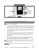
Select a location for the Indoor Unit Mounting Plate (4) to be mounted to the inte-
rior wall, preferably, near a 120 volt, grounded, electrical outlet.
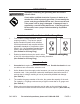
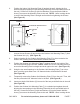
SCREW
(5)
WASHER
(5)
WALL ANCHOR
(5)
5 FT.
INDOOR UNIT MOUNTING PLATE
(4)
FIGURE C
Position the Indoor Unit Mounting Plate (4) against the wall, with its large rectan-
gular opening at top, its four mounting prongs facing outward from the wall, and
at a height of ve feet from the oor surface. NOTE: Make sure to use a leveling
device (not included) to ensure the Mounting Plate is straight and level against
the wall. (See Figure C.)
Using the four small rectangular openings in the Indoor Unit Mounting Plate (4)
as a template, mark the spots where four 1/8” diameter holes will be drilled in the
wall. (See Figure C.)
Temporarily remove the Indoor Unit Mounting Plate (4) from the wall. Then, drill
the four pre-marked 1/8” diameter holes in the wall. (See Figure C.)
Insert one plastic Wall Anchor (5) into each of the four pre-drilled holes in the
wall. (See Figure C.)
1.
2.
3.
4.
5.
CAUTIONCAUTION
WARNINGWARNING