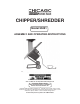
CHIPPER/SHREDDER Model 95091 ASSEMBLY AND OPERATING INSTRUCTIONS Do to continuing improvements, actual product may differ slighlty from the product described herein. ® 3491 Mission Oaks Blvd., Camarillo, CA 93011 Visit our Web site at: http://www.harborfreight.com TO PREVENT SERIOUS INJURY, READ AND UNDERSTAND ALL WARNINGS AND INSTRUCTIONS BEFORE USE. © Copyright 2007 by Harbor Freight Tools®. All rights reserved.
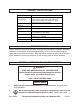
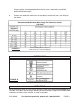
PRODUCT SPECIFICATIONS Item Electrical Requirements Description 120 VAC / 60 Hz / 3400 RPM Power Switch: Rocker Switch with Safety Key Power Cord: 14 AWG x 3 C (SJT) / 5’3” Long Power Plug: 3-Prong / Grounded Up to 1-1/4” Diameter Maximum Limb Capacity Feed Inlet Size Hopper Opening Size Wheel Type 5-1/2” Long x 1-1/2” Wide 14-1/2” Long x 10-3/4” Wide Cutter Blade Overall Dimensions Net Weight Solid Rubber with Plastic Hub 6-1/4” Diameter x 1-3/8” Wide Single Blade Chipper Wheel 3-1/8” Long x 1-3/8” Wi
sparks which may ignite the dust or fumes. 3. Keep bystanders, children, and visitors away while operating a power tool. Distractions can cause you to lose control. Provide barriers or shields as needed. Children should never be allowed in the work area. ELECTRICAL SAFETY 4. Grounded tools must be plugged into an outlet properly installed and grounded in accordance with all codes and ordinances. Never remove the grounding prong or modify the plug in any way. Do not use any adapter plugs.
operating power tools may result in serious personal injury. 11. Dress properly. Do not wear loose clothing or jewelry. Contain long hair. Keep your hair, clothing, and gloves away from moving parts. Loose clothes, jewelry, or long hair can be caught in moving parts. 12. Avoid accidental starting. Make sure the Power Switch is off before plugging in. Carrying power tools with your finger on the Power Switch, or plugging in power tools with the Power Switch on, invites accidents. 13.
the tool serviced before using. Many accidents are caused by poorly maintained tools. 22. Use only accessories that are recommended by the manufacturer for your model. Accessories that may be suitable for one tool may become hazardous when used on another tool. SERVICE 23. Tool service must be performed only by qualified repair personnel. Service or maintenance performed by unqualified personnel could result in a risk of injury. 24. When servicing a tool, use only identical replacement parts.
Chipper/Shredder. Use a stick to push the tree limbs, leaves, etc. into the feed Hopper. 10. Make sure the plastic cover on the Hopper is closed when the machine is running. 11. Always feed large branches slowly into the machine. Branches larger than 1-1/4” diameter should never be fed into the machine. 12. Do not allow processed material to build up in the discharge area. This may prevent proper discharge and can result in kickback of material through the feed Hopper. 13.
GROUNDING WARNING! Improperly connecting the grounding wire can result in the risk of electric shock. Check with a qualified electrician if you are in doubt as to whether the outlet is properly grounded. Do not modify the power cord plug provided with the tool. Never remove the grounding prong from the plug. Do not use the tool if the power cord or plug is damaged. If damaged, have it repaired by a service facility before use.
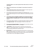
only wire connected to the tool’s grounding system and must never be attached to an electrically “live” terminal. (See Figure B.) 3. The Chipper/Shredder must be plugged into an appropriate outlet, properly installed and grounded in accordance with all codes and ordinances. The plug and outlet should look like those in the following illustration. (See Figure B.) THIS PRODUCT USES A 3-PRONG PLUG 120 VOLT GROUNDED ELECTRICAL OUTLET FIGURE B EXTENSION CORDS 1.
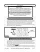
Always replace a damaged extension cord or have it repaired by a qualified electrician before using it. 8. Protect your extension cords from sharp objects, excessive heat, and damp or wet areas. Recommended Minimum Wire Gauge For Extension Cords* (120 Volt) FIGURE C * Based on limiting the line voltage drop to five volts at 150% of the rated amperage. SYMBOLOGY FIGURE D UNPACKING When unpacking, check to make sure all the parts shown on the Parts List on page 15 are included.
ASSEMBLY INSTRUCTIONS 1. CAUTION! Make sure the Power Switch (42) of the Chipper/Shredder is in its “OFF” position and the unit is unplugged from its electrical outlet prior to performing assembly procedures. To Attach The Wheels: 1. Move the Chipper/Shredder to a clean, dry, level area in which to perform the necessary assembly. 2. Place one Washer (24) on each end of the Axle (25). (See Figure E.) 3. Insert the ends of the Axle (25) through the two Vertical Frames (15). (See Figure E.) 4.
Housing (11), making sure to align the two mounting holes in the Chute Cover (7) with the two threaded mounting holes in the Shredder Housing. (See Figure F.) 2. Insert the Hopper (1) into the Chute Cover (7), making sure to align the two mounting holes in the Hopper with the two mounting holes in the Chute Cover (7). (See Figure F.) 3. Place a Washer (3) on two Philip’s Head Screws (8).
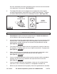
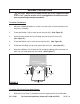
4. CAUTION! Make sure the Chipper/Shredder is empty of material prior to starting the unit. 5. Check to make sure the Wing Nut (36) is securely tightened. (See Figure G.) 6. Check to make sure the Power Switch (42) is in its “OFF” position. Then plug the Power Cord of the unit into the nearest 120 volt, grounded, electrical outlet. (See Figure G.) 7. NOTE: The Power Switch (42) features a Safety Key to prohibit unauthorized people from turning on the Chipper/Shredder.
11. Without putting your hands into the Hopper (1), slowly drop the material into the Hopper (one branch at a time). The machine will pull the material in automatically. (See Figure G.) 12. WARNING! Never use your hands to feed material into the Hopper (1). If needed, use a stick to push the branches, leaves, etc. into the Hopper. (See Figure G.) 13. Always stand clear and to the side of the Discharge Chute located at the bottom of the Chipper/Shredder. (See Figure G.) 14.
If abnormal noise or vibration occurs, have the problem corrected before further use. Do not use damaged equipment. 3. To clean the unit, use a clean cloth and mild detergent. Do not use solvents. Do not expose the electrical parts of the machine to water or any other liquids. 4. CAUTION! All maintenance, service, or repairs not mentioned in this manual must only be performed by a qualified service technician. TROUBLESHOOTING Problem Motor will not start. Possible Cause 1.
PLEASE READ THE FOLLOWING CAREFULLY THE MANUFACTURER AND/OR DISTRIBUTOR HAS PROVIDED THE PARTS LIST AND ASSEMBLY DIAGRAM IN THIS MANUAL AS A REFERENCE TOOL ONLY. NEITHER THE MANUFACTURER OR DISTRIBUTOR MAKES ANY REPRESENTATION OR WARRANTY OF ANY KIND TO THE BUYER THAT HE OR SHE IS QUALIFIED TO REPLACE ANY PARTS OF THE PRODUCT.
ASSEMBLY DIAGRAM NOTE: Some parts are listed and shown for illustration purposes only, and are not available individually as replacement parts.
ELECTRICAL SCHEMATIC SKU 95091 For technical questions, please call 1-800-444-3353 PAGE 17
IMPORTANT WARRANTY INFORMATION LIMITED 90 DAY WARRANTY Harbor Freight Tools Co. makes every effort to assure that its products meet high quality and durability standards, and warrants to the original purchaser that this product is free from defects in materials and workmanship for the period of 90 days from the date of purchase.