.5 HP 7” BRIDGE TILE SAW Model 98265 SET UP AND OPERATING INSTRUCTIONS Note: Stand (SKU 98328) and Diamond Blade sold separately. Visit our website at: http://www.harborfreight.com Read this material before using this product. Failure to do so can result in serious injury. SAVE THIS MANUAL. Copyright© 2008 by Harbor Freight Tools®. All rights reserved.
CAUTION, without the safety alert symbol, is used to address practices not related to personal injury. SAVE THIS MANUAL Keep this manual for the safety warnings and precautions, assembly, operating, inspection, maintenance and cleaning procedures. Write the product’s serial number in the back of the manual near the assembly diagram (or month and year of purchase if product has no number). Keep this manual and the receipt in a safe and dry place for future reference.
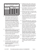
RECOMMENDED MINIMUM WIRE GAUGE FOR EXTENSION CORDS (120 VOLT) NAMEPLATE AMPERES (at full load) EXTENSION CORD LENGTH 25’ 50’ 100’ 150’ 0–6 18 16 16 14 6.1 – 10 18 16 14 12 10.1 – 12 16 16 14 12 12.1 – 16 14 12 Do not use. TABLE A 9. USE PROPER EXTENSION CORD. Make sure your extension cord is in good condition. When using an extension cord, be sure to use one heavy enough to carry the current your product will draw.
3-pole receptacles that accept the tool’s plug. GROUNDING INSTRUCTIONS TO PREVENT ELECTRIC SHOCK AND DEATH FROM INCORRECT GROUNDING WIRE CONNECTION READ AND FOLLOW THESE INSTRUCTIONS: 6. Grounding Pin 110-120 V~ Grounded Tools: Tools with Three Prong Plugs 1. In the event of a malfunction or breakdown, grounding provides a path of least resistance for electric current to reduce the risk of electric shock.
6. Do not perform any operation freehand. 7. Never reach around or over saw blade. 8. Make sure the workpiece is supported at all times while sawing. Use a roller stand (not provided) with larger workpieces if necessary. 9. To properly understand all safety warnings, be familiar with the following safety terms and equipment: a. Featherboard – A block with “fingers“ that hold the workpiece against the fence while sawing. b.
check that the saw teeth are not engaged into the workpiece before turning on the saw. • Push the wood stock past the blade prior to release. 11. Check guards for proper operation with saw disconnected from power before each use. Do not disable any guard. Do not operate saw if any movable guard does not move freely and close instantly. Make sure any movable guard does not touch the blade in all angles, depths of cut, and positions. 12. Keep the guard in place while throughsawing.
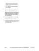
Essential Straight Push-stick Features and Functions Note: Straight style (traditional) stick shown. A different stick design may be used if it properly protects against all hazards. Diagram not to scale. Handle Notch • Must be far enough down the stick to allow a comfortable and firm grip. • Push sticks must be made from sturdy, defect-free, plywood or normal wood to prevent unexpected breakage. Material must be at least 1/4” thick, but no thicker than the finished wood.
POSITION OF TILE SAW 1. 2. To avoid the possibility of the tool plug or receptacle getting wet, position tile saw to one side of a wall mounted receptacle to prevent water from dripping onto the receptacle or plug. The user should arrange a “drip loop” in the cord connecting the saw to a receptacle. The “drip loop” is that part of the cord below the level of the receptacle, or the connector if an extension cord is used, to prevent water traveling along the cord and coming in contact with the receptacle.
12. Industrial applications must follow OSHA guidelines. 13. Maintain labels and nameplates on the tool. These carry important safety information. If unreadable or missing, contact Harbor Freight Tools for a replacement. depending on how often you do this type of work. To reduce your exposure to these chemicals: work in a well ventilated area, and work with approved safety equipment, such as those dust masks that are specially designed to filter out microscopic particles.
fingers), seek medical advice as soon as possible. 2. Do not smoke during use. Nicotine reduces the blood supply to the hands and fingers, increasing the risk of vibrationrelated injury. 3. Wear suitable gloves to reduce the vibration effects on the user. 4. Use tools with the lowest vibration when there is a choice between different processes. 5. Include vibration-free periods each day of work. 6. Grip tool as lightly as possible (while still keeping safe control of it). Let the tool do the work.
SPECIFICATIONS Maximum Blade Diameter 7" Arbor Hole 5/8" Maximum Cutting Capacity 1-1/8" @ 90° 3/4" @ 45° Tilting Head 45° Left-Tilt only Electrical Requirements 120 V~ / 60 Hz / 10 A Blade Rated Speed 5000 RPM Water Pump Maximum Flow = 160 GPH Stand (SKU 98328) Sold separately Note: Recommend Blades: SKU 67047: 7” Turbo Diamond Blade (Wet or Dry) (sold separately) SKU 67111: 7” Diamond Wet Blade (sold separately) TO PREVENT SERIOUS INJURY FROM ACCIDENTAL OPERATION: Turn the Power Switch of
Mounting This tool can be placed on a table or other stable surface. The ideal method would be to mount the tile saw on the stand made for it, SKU 98328 (not included, sold separately). OPERATING INSTRUCTIONS Read the ENTIRE IMPORTANT SAFETY INFORMATION section at the beginning of this manual including all text under subheadings therein before set up or use of this product. Fig. 1 4. The Handle (B13) must be installed onto the Holder (B09) using the two supplied Hex Screws (B12). (See Fig. 1.
General Operating Instructions Power Switch Knob Sliding Bar Support Bevel Scale Reset Button Fig. 4 Fig. 3 1. When making a flat cut, slide the piece to be cut up against the two Fence (D09,D12) halves securely and stabilize one side with the provided Clamp Plate. 2. When making an angled cut, position one end securely at the point where the two Fence halves come together. Use the Clamp Plate to secure it. The cut-off side of the workpiece must be free to move away from the blade to prevent binding.
Maintenance, And Cleaning” section of this manual. Use of unauthorized parts or failure to follow maintenance instructions may create a risk of electric shock or injury. MAINTENANCE AND SERVICING Procedures not specifically explained in this manual must be performed only by a qualified technician.
5. Remove the blade and replace with a new one. Make sure the arrow on the blade matches the direction of the arrow embossed on the blade cover. move the plug and drain the water and silt accumulated by the cutting operation. 3. Use more water to clean out the residual silt from the water tray. 6. With the flat wrench in place again, reinstall the blade’s hex bolt turning clockwise, and tighten securely. 4. 7. Replace the clear Cover and secure with the three Hex Screws removed earlier.
PARTS LIST AND ASSEMBLY DIAGRAM A (MOTOR) Part A01 A02 A03 A04 A05 A06 A07 A08 A09 A10 A11 A12 A13 A14 A15 A16 A17 A18 Description Screw (M5x12) Hose Connect Water Tubing Screw (M5x10) Inner Flange Bearing (6202RT) Washer (14) Bearing (628-R) Grounding Wire Front Motor Cover Outer Teeth Washer Screw (M4x8) Guard Screw (STS.
PARTS LIST AND ASSEMBLY DIAGRAM B (HANGER) Part B01 B02 B03 B04 B05 B06 B07 B08 B09 B10 B11 B12 B13 B14 Description Screw (M4x6) Screw (M4x20) Hex Nut (M4) Linear Bushing Felt Bushing Seal Bearing Hex Bolt (M6x20) Holder Knob Flat Washer Screw (M5x12) Handle End Cap Qty. 3 1 1 2 4 4 4 4 1 1 2 2 1 2 REV 10b SKU 98265 For technical questions, please call 1-800-444-3353.
PARTS LIST AND ASSEMBLY DIAGRAM C (SUPPORT) Part C01 C02 C03 C04 C05 C06 C07 C08 C09 C10 C11 C12 C13 C14 C15 Description Steel Support B Connection Shaft Set Screw (M4x15) Flat Washer Knob Socket Wrench Spring Washer Flat Washer Wrench Holder Sliding Bar Support Screw (M6x8) Bevel Scale Flat Washer Spring Washer Hex Nut Qty.
PARTS LIST AND ASSEMBLY DIAGRAM D (WORK TABLE) Part D01 D02 D03 D04 D05 D06 D07 D08 D09 D10 D11 D12 D13 D14 D15 Description Hex Nut (M6) Spring Washer Flat Washer Stainless Steel Frame Hex Bolt (M6x30) Table End Right Fence Cover 1 Scale Right Fence Right Fence Cover 2 Left Fence Cover 1 Left Fence Scale Left Fence Cover 2 Hex Bolt (M6x15) Qty.
PARTS LIST AND ASSEMBLY DIAGRAM E (WATER TRAY) Part EO1 EO2 EO3 EO4 EO5 EO6 EO7 EO8 Description Water Tray O-Ring Drain Plug Rubber Cap Flat Washer Set Screw Rubber Feet Carrying Handle Grip Qty. 1 1 1 1 7 11 7 2 REV 10b Page 20 For technical questions, please call 1-800-444-3353.
LIMITED 90 DAY WARRANTY Harbor Freight Tools Co. makes every effort to assure that its products meet high quality and durability standards, and warrants to the original purchaser that this product is free from defects in materials and workmanship for the period of 90 days from the date of purchase.