0
IMPORTANT NOTICES IMPORTANT Before operating or maintaining this unit, please read this manual carefully paying extra attention to the safety warnings and precautions. www.maxidas.com www.auteltech.com 1-855-288-3587/ 1-855-AUTELUS (North America) support@auteltech.com For technical assistance in all other markets, contact your selling agent.
Contents IMPORTANT NOTICES .................................................................... 1 SAFETY INFORMATION ....................................................................... I 1. Introduction ..................................................................................... 1 1.1. 1.2. 2. 3. 4. Product Overview .............................................................................. 1 Component Descriptions................................................................... 1 1.2.
.1. 4.2. 4.3. 4.4. 4.5. 5. 6. 7. General Procedures ......................................................................... 58 Play Back.......................................................................................... 59 Data Logging.................................................................................... 59 Screen Capture ................................................................................ 61 Printing....................................................................
SAFETY INFORMATION DANGER: When an engine is operating, keep the service area WELL VENTILATED or attach a building exhaust removal system to the engine exhaust system. Engines produce carbon monoxide, an odorless, poisonous gas that causes slower reaction time and can lead to serious personal injury or loss of life. SAFETY DEFINITIONS Follow all DANGER, WARNING, IMPORTANT, and NOTE messages in this manual.
Put blocks in front of the drive wheels and never leave the vehicle unattended while running tests. Use extreme caution when working around the ignition coil, distributor cap, ignition wires and spark plugs. These components create hazardous voltages when the engine is running. Keep a fire extinguisher suitable for gasoline/ chemical/ electrical fires nearby. Don’t connect or disconnect any test equipment while the ignition is on or the engine is running.
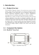
1. Introduction 1.1. Product Overview The MaxiDAS® Diagnostic System is the easiest-to-use scan tool which features simple touch screen navigation. It is ingeniously designed to create the functionality of the OEM tools used by automotive manufacturer’s dealers, empowering independent garages to provide comprehensive servicing in their own workshops without relying on dealer availability. MaxiDAS® has a memory card that contains the operating system and scan software applications.
Figure 1.2: MaxiDAS® Back View Figure 1.3: MaxiDAS® Top View Figure 1.4: MaxiDAS® Down View ① Touch Screen Display - displays the menus and data screens. ② LEDs - the three light-emitting diodes indicate certain system conditions. Wireless LAN Activity LED - illuminates when a wireless local area network (LAN) is enabled, flashes when data is being sent or received. Vehicle Communication LED - illuminates when the scan tool is communicating/linking with systems of the vehicle being tested.
③ Rubber Boot - protects the scan tool from accidental damage if dropped. ④ Stylus Pen - selects items and enters information. ⑤ Stand - flips out for setting the scan tool in an upright position. ⑥ External DC Power Port - connects the 12 volt power adapter to power the tool for updating, printing, Internet access, and etc. when disconnected from the vehicle. ⑦ USB (universal serial bus) Port - connects peripheral devices such as printers, and portable USB Drives.
1.2.3. DLC Cables, Adapters and other Accessories 1. DLC Cables The DS708 unit can be powered through the DLC cable when connected to an OBD-II vehicle. The DLC cable connects the scan tool to the vehicle’s data link connector (DLC). An optional extension cable may also be used. Figure 1.6: DLC Cable 2. OBD I Adapters The OBD I adapters are for Non-OBD II vehicles. The adapters used depend on the type of vehicle make being tested. The most common adapters are shown below.
BMW-20 Kia-20 GM/Daewoo-12 Mitsubishi/Hyundai12+16 Audi-4 Benz-38 Fiat-3 PSA-2 Figure 1.7: OBD I Adapters 3. Other Accessories RS232 Serial Cable Connects the scan tool to the Ethernet network. Clipper Cable Provides power to the scan tool through connection to the vehicle battery as some non-OBD II vehicles cannot provide power to the scan tool via DLC connection. AC/DC External Power Adapter Connects the scan tool to the External DC Power Port for external power supply.
Compact Disc (CD) Includes the Instruction Video Clip, the User’s Manual, remote desktop, print services, update application, and etc. Cigarette Lighter Provides power to the scan tool through connection to the vehicle’s cigarette lighter receptacle as some non-OBD II vehicles cannot provide power to the scan tool via DLC connection. SD Card Reader Allows files on the SD card to be accessed to a PC. 1.2.4.
1.3. Software Descriptions This section describes the software currently available for the scan tool. NOTE: This section does not describe any PC software that is used along with the scan tool. 1.3.1. Operating System Software The operating system is Microsoft Windows CE Embedded. When you turn the scan tool on, the software provides fast “boot-up” and an icon-based application home screen. 1.3.2.
Figure 1.8: Home Screen With the Home Screen displayed, you use either the stylus pen or a finger to select an option to display the icons to choose. The options on the Home Screen are described in the next few sections as follows: USA European Asian Data Manager Update Setup/Help 2. USA When you click on USA from the Home Screen (Figure 1.8), the USA screen appears, as shown in the example below. Figure 1.
3. European When you click on European from the Home Screen (Figure 1.8), the European screen appears, as shown in the figure below. Figure 1.10: European Screen This screen contains options for using the diagnostic software applications for European vehicles. 4. Asian When you click on Asian from the Home Screen (Figure 1.8), the Asian screen appears, as shown in the example below. Figure 1.
This screen contains options for using the diagnostic software applications for Asian vehicles. 5. Data Manager When you click on Data Manager from the Home screen (Figure 1.8), the Data Manager screen appears, as shown below. Figure 1.12: Data Manager Screen This screen contains options for using the functions of playback, data logging and screen capture. a. Playback Function The Playback function allows you to view data recorded with various functions.
Figure 1.13: Playback Screen b. Data Logging Data logging is the process of recording events in order to provide a collection of data that can be used to diagnose vehicle communication problems. It can benefit the users by providing quick fix to software problems from the engineers. When you click on the Data Logging icon from the Data Manager Screen (Figure 1.12), the Data Logging screen appears, as shown below. Figure 1.14: Data Logging Screen For details, refer to Chapter IV Data Manager & Printing. c.
The Screen Capture function is used to take an image by the scan tool to record the visible items displayed on the monitor. The screen shots can be used to demonstrate a particular problem a user might be having so that he can show the output to customer support engineers for help. When you select the Screen Capture icon from the Data Manager screen (Figure 1.12), the Screen Capture screen appears, as shown below. Figure 1.15: Screen Capture Screen For details, refer to Chapter IV Data Manager & Printing.
Figure 1.16: Update Screen 7. Setup/Help Functions When you click on Setup/Help from the Home Screen (Figure 1.8), the Setup/Help screen appears, as shown below: Figure 1.17: Setup/Help Screen This screen contains options for viewing information about the scan tool and adjusting default settings for the scan tool as follows: Wi-Fi - sets up the Wi-Fi network. Network - sets up the Ethernet network. Unit - sets the unit of measure. Date/Time - sets the date and time.
Language - sets the default language for the scan tool software. Backlight - adjusts the backlight of the screen. Beep - sets the beep of the scan tool. Touch - calibrates the touch screen. Remote Desk - sets the remote desk. Workshop Info – provides information about workshop and mechanics. About - provides information about the scan tool, such as software version, operating system software version, hardware version, product serial No., etc.
2. Getting Started 2.1. Power up the Scan Tool NOTE: BEFORE USING THE SCAN TOOL, ENSURE TO PEEL OFF THE PROTECTIVE MASK COVERED ON THE SCREEN. To power on the scan tool, you must provide power to the scan tool. There are two methods for providing power to the scan tool: AC/DC external power adapter Cable connection to vehicle During vehicle testing, power for the scan tool is usually provided through the vehicle cable connection.
Figure 2.2: Setup/Help Screen 3. Select an item to adjust. 4. Follow any on-screen instructions. 5. For detailed instructions, refer to Chapter V System Setup. 2.3. Install the PC Software MaxiDAS® allows you to realize some of its functions on a PC for convenience and better experience. To realize these functions on a PC, users are required to install certain software into the computer. The Setup.exe software package is contained in the Compact Disc (CD) provided.
Follow these steps to install the software: 1. Insert the CD into the CD-ROM of your computer. 2. An Install Shield Wizard window will pop up. Click on Next to continue. Figure 2.3: Install Shield Wizard Window 3. The next screen indicates the destination folder to install the software. Click on the Change button, select a folder, and click on Next to continue. Or, directly click on Next to continue. Figure 2.
4. Click on Install to begin the installation. Figure 2.5: To Start Installation 5. Click on Finish to complete the installation process. Figure 2.
2.4. Register the Tool User would enjoy our service Only after you had registered the tool on our website:www.maxidas.com. Then you could download software, update online, retrieve information and get warranty service. Before you finish registration, a message will pop up every time the tool is powered on. There are three ways to register the scan tool. Prior to registration, please confirm your network is working properly. A. Register on Internet 1. Log on the website www.maxidas.com. 2.
NOTE: Please use the System/Help > About function to find out the Product Serial No. and Register Password. For details, please refer to the Section 5.11 About. Or, you could find the information on the pop-up registration MessageBox (Figure 2.8). 6. Turn on the scan tool and wait 30 seconds for the registration message to disappear. Then click on Update from the Home Screen to display the Update window. Select the Exit button on the screen to shut down. Figure 2.8: Exit Update program 7.
NOTE: No update can be carried out before the tool is registered. If Update is selected, the update screen will show as follow: Figure 2.10: Prompt box for registration-in Update 1. Click on Register button in the popup MessageBox and activate Register Wizard. Figure 2.11: Register Wizard- step 1 2. Click on Next to start registration. The scan tool will automatically connect to Autel Server. Follow the steps in “A. Register on Internet” to register your tool on Internet. 3.
Figure 2.12: Register Wizard- step 2 4. Then click on Close in the Register Wizard to shut down the program. Figure 2.13: Register Wizard- step 3 5. Restart the scan tool to finish registration procedure. C. Register on computer You may register the scan tool by two softwares. 1. DS708 Register Wizard Insert the SD card into your computer and run the DS708 Register Wizard. Follow the step2 to step4 in “B. Register on the scan tool” to complete registration to SD card.
2. DS708 Update Insert the SD card into your computer and run the DS708 Update. There is a Register option in the log-in window (figure 6.3). When click on it, it will automatically link to DS708 Register Wizard. Follow the step2 to step4 in “B. Register on the scan tool” to complete registration to SD card. Put the SD card back to the scan tool and restart it to finish registration procedure. 2.5. Test Startup and Vehicle Connection Step 1: Connect the Cable. Step 2: Enter the Vehicle information.
3. Diagnostics Applications 3.1. Test Startup and Vehicle Connection 3.1.1. Step 1: Connect the Cable The method used to connect the scan tool to a vehicle’s DLC depends on the vehicle’s configuration as follows: A vehicle equipped with an On Board Diagnostics Two (OBD II) vehicle management system supplies both communication and 12-volt power through a standardized J-1962 data link connection (DLC).
Figure 3.2: Main Cable Connection to the Scan Tool NOTE: Extension cable can be used between the scan tool and the 15-pin main cable. Connect the cable’s OBD II adapter into the vehicle’s DLC, located under the vehicle dash. Figure 3.3: OBD II Cable Connection to Vehicle DLC b.
and power is to be supplied through cable connection to vehicle battery. This type of connection generally requires the vehicle-specific OBD I adapter and the 15-pin main cable. To connect the DB15 main cable or another similar cable, please follow these steps: 1. Locate the required OBD I adapter and connect the adapter’s 15-pin adapter to the cable’s 15-pin male adapter. Figure 3.4: OBD I Adapter Connection to the DB15 Main Cable 2.
Figure 3.6: Main Cable Connection to Vehicle DLC If the DLC connection does not supply power to the scan tool, connection to the cigarette lighter receptacle will be needed. Please follow these steps: 1. Connect the cigarette lighter with the scan tool. Figure 3.7: Cigarette Lighter Connection to the Scan Tool 2. Connect the cable’s power plug into the vehicle’s cigarette lighter receptacle.
Figure 3.8: Plug into the Vehicle’s Cigarette Lighter Receptacle NOTE: The vehicle’s DLC is not always located under the dash as shown above. NOTE: Some adapters may have more than one adapter or may have test leads instead of an adapter. Whatever the case, make the required connections to the vehicle’s DLC. If the cigarette lighter connection does not provide power either, connection to the vehicle’s battery is necessary. Follow these steps: 1. Connect the cigarette lighter to the clipper cable. Figure 3.
WARNING: The clippers might be hot after use. Be careful not to be burnt. You can conveniently obtain power supply through power adaptor connection to the scan tool if any power socket is within reach. Figure 3.10: Power Adapter Connection to the Scan Tool 3.1.2. Step 2: Enter the Vehicle Information and Select the System to Be Tested NOTE: The screens shown below in this User’s Manual are examples. The screens actually appear vary by vehicle.
2. Select the vehicle manufacturer group. This displays the vehicle manufacturer screen. Figure 3.12: Vehicle Manufacture Group Screens 3. With the Vehicle Information screen displayed, you can enter the vehicle information either by selecting the correct option step by step or acquiring the vehicle VIN manually or automatically. Figure 3.
testing. For most others, you must enter the vehicle information before you can do any testing. For vehicles like BENZ, both selecting the option manually and acquiring the VIN are available for you to enter the vehicle information. Do one of the following: To select the correct option step by step, go to step 4 and then step 6. To acquire the vehicle VIN manually or automatically, go to step 5 and then step 6. 4.
5. To acquire the vehicle VIN manually or automatically, do the following: Select VIN acquisition. This displays the VIN acquisition screen, which may contain two options for you to choose: automatic acquisition or manual acquisition. Select either automatic acquisition or manual acquisition to acquire the VIN. Figure 3.15: Manual VIN Acquisition Screen 6. After you have entered the vehicle information, the diagnostic testing selection screen will display as below: Figure 3.
vehicle one by one. Auto Scan will take a few minutes. NOTE: The Control Unit option will list down all the systems that might be available on the vehicle for you to select to test. Do one of the following: To select Auto Scan, go to step 7 and then step 9. To select Control Unit, go to step 8 and then step 9. 7. Select Auto Scan, and the following screen will display: Figure 3.
Figure 3.18: Reading Status Screen NOTE: You can save the Auto Scan information as “Vehicle Record” so that you will not need to follow the vehicle selection process again on the same vehicle in later tests. For detailed instructions, please refer to the steps. 8. Select Control Unit, and the following screen will display: Figure 3.19: Control Unit System Menu Screen 9. Select a system to display the function menu and start testing.
Figure 3.20: Function Menu Screen To save a vehicle record, please follow these steps: 1. Please follow the instructions above to display the Auto Scan menu. Figure 3.21: Auto Scan System Menu Screen 2. When the Auto Scan process is done, click on the Save button, and name the record on the Save Vehicle Record screen.
Figure 3.22: Save a Vehicle Record 3. To enter the diagnostic functions through the vehicle record option in future, please follow these steps: Select Vehicle Data Record from the vehicle selection menu. Figure 3.23: Vehicle Selection Menu Screen Click on the Vehicle Data Record option to enter the diagnostic menu directly. Figure 3.24: Select a Vehicle Record 3.1.3.
codes set by the vehicle ECU(s). For details, refer to Section 3.2 Diagnostic Trouble Codes. Select Live data to view real time streaming data of sensors and switches from the vehicle ECU(s). For details, refer to Section 3.3 Live data. Select Vehicle Information to view vehicle-specific information, such as TSBs, specifications, component locations, etc. For details, refer to Section 3.4 Vehicle Info.
1. With the Function Menu screen displayed, click on Read Codes. This displays the Read Codes menu screen. Figure 3.26: Read Codes Screen 2. Click on one of the options that may appear on the Read Codes screen. Save - saves the code results for later review. Print - prints the code results. 3. When finished viewing the list, click on the Esc button to return to previous screens. NOTE: When a Benz is being tested, DTC will be stored in two forms: Fault Codes and Event Memory.
3.2.2. Erase Codes After reading and / or reviewing the diagnostic trouble codes, use the following steps to erase the codes from the vehicle. If Erase Codes is not an available menu option, consult the manufacturer’s service manual for the correct “clear code” method. NOTE: This Erase Codes function clears the DTCs from the selected ECU or provides instructions for how to manually clear the codes from the ECU.
Figure 3.28: Function Menu Screen 2. Click on Live Data. This displays the Live Data screen. NOTE: Optionally, you can use Custom Live Data and select specific live data items for viewing. For details, refer to the Sub-Section 3.3.3 Custom Live Data. Figure 3.29: Live data Screen 3. Notice the following about the Live Data screen: Each line displays a data item.
You can stop and start the live readings at any time by clicking on the Pause button. When you stop the readings, the data “freezes” on the screen. The function keys and options at the top and on the right of the screen allow you to perform several other functions on the screen. For details, refer to Sub-Section 3.3.2 Live Data Functions. 4. When you are finished using the screen, click on ESC to return to the Function Menu screen. 3.3.
Figure 3.30: Live Data Screen To change the display, click on the Digital/ Graph / Graph Merge/ Analog function buttons. a. About Digital Display When the data is displayed as Digital, its reading is a word or a number as shown below. Figure 3.31: Live Data Screen-Digital Display You can change the display of the lines as follows: If the reading is a word (usually a switch reading), such as On, Off, OK, etc., the display can only be in word format.
b. About Graph Display If the data reading is a number (usually a sensor reading), such as 14.4 V, 1.1 V, or 23 Amps, you can use the Graph/ Graph Merge function buttons to display the data in graph format. For example, see Figures 3.32 and 3.33. Figure 3.32: Live Data Screen-Graph Display Figure 3.33: Live Data Screen-Graph Merge Display c. About Analog Display If the data reading can be displayed as a graph (see Figures 3.32 and 3.
Figure 3.34: Live Data Screen - Analog Display 2. Record Data The Record function allows you to save data files to the SD card and then use the Playback function to view the saved files. NOTE: The length of time for each frame varies per vehicle. Generally, one frame of data is about 1/4 of a second, or 4 frames per second. To record to SD Card, please follow these steps: 1. Follow the steps in the Sub-Section 3.3.1 Basic Live Data Procedure to display the Live Data screen. Figure 3.
Temporarily shades the Save function button. Automatically records the frames of data that occur after clicking on the button. NOTE: You can record any number of files as long as they fit on the free space on the SD card. To stop recording, just click on the Stop function button. 3. When the recording stops, continue viewing live data or use the ESC button to return to previous screens. 4. To view the saved data file, refer to Section 4.2 Playback. 3.
currently displayed on the screen. To print the data, please follow these steps: NOTE: The scan tool must be connected to the Internet, and some operations shall be done on a PC. Refer to Section 4.5 Printing. Figure 3.37: Live data Screen - Print Function 1. With the Live Data screen displayed, click on the Print button to select the Print function. 2. The message “Print the current frame of data?” appears on a Print screen. Click on the OK function key. 3.
Figure 3.38: Function Menu Screen 2. Click on Custom Live Data. This displays the Custom Live Data selection screen. Figure 3.39: Custom Live Data Selection Screen – before Selection 3. Select the data items to include in the Live Data display as follows: Click on the data item to select. A check mark appears in the box on the left side of the item. Use the Pg Up or Pg Dn keys to display the data item if the desired data items are not on the current display.
Figure 3.40: Custom Live Data Selection Screen - after Selections NOTE: To deselect an item, select the item again by clicking on the item. Optionally, use the Select All and Clear All function keys to select or deselect all of the items at once. 4. When finished selecting data items, click on the OK function key to display the selected items on the Custom Live Data screen. Figure 3.41: Custom Live Data Screen 3.
Figure 3.42: Function Menu and Vehicle Info Screens 3. View the Vehicle information as displayed. 3.5 Active Test During an active test, a diagnostic tester is used for outputting commands to the ECU in order to drive the actuators. This test determines the integrity of the system or parts by monitoring the operation of the actuators or by reading the engine ECU data. Performing the Active Tests using the hand-held tester allows the relay, VSV, actuator and etc to operate without parts removal.
2. Select Active Test and a list of possible tests appears. Figure 3.44: Active Tests List Screen 3. Select a test, and the scan tool will display an information screen of “Are you sure you want to start?” Click on Start to continue or Esc to exit. 4. The scan tool may display information during and after the test. The information varies by vehicle. Figure 3.45: Active Test Information Screens IMPORTANT: Make sure that the components to be tested are not physically damaged and are well assembled.
WARNING: Please stop repairing the components to be tested before the test starts and keep a certain distance during the test. 3.6 Generic OBD II Functions The OBD II Diagnostics function is a fast-access option that allows you to carry out a quick test on the engine system of OBD II vehicles. 3.6.1. General Procedures To access the ODBII diagnostics functions, please follow these steps: 1. Power up the screen to display the home screen (Figure 1.8). 2. Click on the OBD II icon.
I/M Readiness O2 Mon. Test On-Board Mon. Test Component Test Vehicle Info. Modules Present DTC Lookup NOTE: Some functions are supported only on certain vehicle makes. 3.6.2. Functions Description 1. System Status The System Status function allows you to view system status of the vehicle being tested. Figure 3.47: OBD II-System Status Screen 2. Read Codes Reading Codes can be done with the key on engine off (KOEO) or with the key on engine running (KOER).
Figure 3.48: OBD II-Read Codes Screen 3. Erase Codes The Erase Codes function allows you to delete diagnostic trouble codes, Freeze Frame data and manufacturer specific enhanced data from the vehicle’s on-board computer, and resets the I/M Readiness Monitor Status for all vehicle monitors to Not Ready or Not Complete status. This function is performed with key on engine off (KOEO). Do not start the engine. 4. Live Data The Live Data function allows you to view real time PID data from ECU.
Figure 3.49: OBD II-Live Data Screen 5. Freeze Frame Freeze Frames function allows you to view data stream “snapshots” automatically recorded by the ECU that show actual data values at the time when DTC(s) occurred. The data can be saved to the SD card, or be printed. Figure 3.50: OBD II-Freeze Frame Screen 6. I/M Readiness I/M Readiness function is used to check the operations of the emission systems.
Figure 3.51: OBD II-I/M Readiness Screen 7. O2 Mon. Test The O2 Monitor Test function allows retrieval and viewing of O2 sensor monitor test results for the most recently performed tests from the vehicle's on-board computer. The O2 Monitor Test function is not supported by vehicles which communicate using a controller area network (CAN). For O2 Monitor Test results of CAN-equipped vehicles, please refer to “On-Board Mon. Test”. The data can be saved to the SD card, or be printed. Figure 3.
Figure 3.53: OBD II-On Board Mon. Test Screen 9. Component Test The Component Test function allows you to command the vehicle’s on-board computer to start a leak test for the vehicle’s EVAP system. Figure 3.54: OBD II-Component Test Screen 10. Vehicle Info. The Vehicle Information function enables retrieval of Vehicle ID Number (VIN), Calibration ID (CIN), Calibration Verification Number (CVN) and In-use Perform Track on 2000 and newer vehicles that support Mode 9.
Figure 3.55: OBD II-Vehicle Info. Screen 11. Modules Present The Modules Present function allows you to view module IDs and communication protocols of OBD II modules in the vehicle. Figure 3.56: OBD II-Modules Present Screen 12. DTC Lookup The DTC Lookup function allows you to search for definitions of DTCs stored in built-in DTC library. Figure 3.
4. Data Manager & Printing The Data Manager functions allow you to playback saved data recordings, as well as accessing the programs of Data Logging and Screen Capture. 4.1. General Procedures To access the Data Manager functions, please follow these steps: 1. Ensure that the scan tool is connected to a power source and the power LED light is illuminated. 2. Press the On/Off button to turn on the scan tool, wait for the home screen to appear. 3.
4.2. Play Back The Playback function allows you to view data saved. It also allows you to save, delete, and print recorded files. 1. Follow the instructions in the General Procedures to display the Data Manager screen. 2. Click on the Playback icon and wait for the Playback screen to show. Figure 4.2: Playback Screen 3. Select the data you wish to view by clicking on it. 4. Click on Esc to return to the previous screen after viewing the data. 5.
2. Click on the disc icon in the upper right corner to display the data logging menu during a diagnostic process when necessary. Figure 4.3: Data Logging Menu 3. Click on “Start data logging”, a dialog box will display. Figure 4.4: Data Logging Dialog Box 4. Use the soft keyboard to put in File Name and File detail, and click on OK. The scan tool will start to record the communication process with the vehicle being tested.
5. Click on the disc icon in the upper right corner to display the data logging menu, and click on “Stop data logging” to stop recording. 6. Do one of the following: Click on “Report” from the data logging menu to enter the Data Logging screen. Or, Follow the instructions in the General Procedures to display the Data Manager screen. Click on the Data Logging icon to enter the Data Logging screen. Figure 4.5: Data Logging Screen 7.
Figure 4.6: Screen Capture Screen 2. Click on the File Name space and wait for the soft keyboard to pop up; use the soft keyboard to modify the file name, if necessary. NOTE: The “Adding Detail” area can be left blank. 3. Click on the Adding Detail space and wait for the soft keyboard to pop up; use the soft keyboard to put in explanations to the picture. 4. Click on Save to save the picture. Detailed description of the last picture saved will be shown in the Old Details space.
Figure 4.7: Screen Capture – Recent Images 3. Click on the screen to zoom in the picture to full screen and click again to zoom out. 4. Use the Prev. or Next buttons to view the previous or next pictures. 5. Use the Delete button to delete the picture being displayed, or use the Delete All button to delete all pictures stored. 6. Click on Esc to return to the Data Manager menu. To print the picture, please refer to the Section 4.5 Printing. 4.5.
Cable network connection. Connect the scan tool to network router with a RS232 Serial Cable supplied. Please refer to section 5.3 Network for detailed instructions. For the computer Ensure that the Print Server software has been properly installed to your computer. Please refer to Section 2.3 Install the PC Software for detailed instructions. Ensure that the computer has been properly connected to a printer. Run the Print Server software on computer. To print the data, follow these steps: 1.
Figure 4.9: Print Server screen 4. Click on the Print icon to print the document. In order to print more easily and smoothly, there are some printing options you can choose. Quick Print : quick-print the document using current options. Print : print the document in a normal procedure. Test Print: print a text page to check if the print function is working properly.
To resolve print failure, you must determine its cause. Causes typically fit one of four major categories: Damaged documents or damaged content in documents The Print Server program The printer driver Connectivity/hardware It is important not to assume too quickly what the cause of your printing problem may be. Instead, rely on systematic troubleshooting to reveal the real cause. Perform the following easy tests to help determine the type of cause that you are experiencing.
Step 2: Test Printing in Other Programs Understanding the scope of the printing problem may reveal its cause. For example, some printing problems only affect the Print Server, and other printing problems affect several or all of your Microsoft Windows programs. The following tests can help determine whether this issue involves multiple programs or whether the symptoms are unique to the Print Server. Test the print function in your Office programs or Web browser.
1. Check the hardware connection status. If using a wireless connection, make sure the distance between the scan tool and router is less than 3 feet. If connection problem persists, please try the cable connection. 2. Check the Print Server program. Reinstall it if needed. If the print problem persists, please contact Autel Tech Support or your local selling agent.
5. System Setup The System Setup functions allow you to adjust default setting and view information about MaxiDAS® DS708. 5.1. General Procedures To access the System Setup functions, please carefully follow the steps below: 1. Ensure that the scan tool is connected to a power source and the power LED light is illuminated. 2. Press the ON/OFF button to turn on the scan tool and wait for the home screen to appear. 3. Click on Setup/Help. This displays the Setup/Help screen. Figure 5.1: Setup/Help Screen 4.
Backlight Beep Touch Remote Desk Workshop Info About 5.2. Wi-Fi The Wi-Fi function allows you to use wireless network connection on the scan tool. 1. Follow the instructions in the General Procedures to display the Setup/Help screen. 2. Click on the Wi-Fi icon and wait for the WLAN Settings window to pop up. Figure 5.2: WLAN Settings Window 3. Select the network you want to connect in the Active Networks column, and click on the Connect button.
4. Wait for an IP address to be assigned. 5. Click on OK to save your configuration and exit. NOTE: If no network is listed in Preferred Networks column or Active Networks column, click on the button to refresh the screen. If refreshing does not help, you will have to add a hidden wireless network manually. To add a hidden wireless network, please do the following: Follow the step 1 and step 2 above in the Section 5.2 Wi-Fi to display the WLAN Settings window.
Select the action which you would accomplish. 5.3. Network The Network function allows you to adjust network settings. 1. Properly insert the network cable into the RS 232 Serial Port of the scan tool. 2. Follow the instructions in the General Procedures to display the Setup/Help screen. 3. Click on the Network icon and wait for “DM9000A/9010 ISA Fast Ethernet Adapter Settings” window to pop up. Figure 5.4: Network 4.
5.4. Unit The Unit function allows you to adjust units of measurement. 1. Follow the instructions in the General Procedures to display the Setup/Help screen. 2. Click on the Unit icon and wait for Unit window to pop up. 3. Select Metric for the metric units of measure or select English for the English units of measure. Figure 5.5: Unit 4. Click on OK to save your configuration and exit or click Cancel to exit without saving changes. 5.5. Date/Time The Date/Time function allows you to set time and date. 1.
5. Select Date Format to change the format of date. Figure 5.6: Date/Time 6. Click on OK to save your configuration and exit or click Cancel to exit without saving changes. 5.6. Language The Language function allows you to adjust language settings. 1. Follow the instructions in the General Procedures to display the Setup/Help screen. 2. Click on the Language icon and wait for the Language window to pop up. 3. Click on a language. Figure 5.
4. Click on OK to save your configuration and exit or Cancel to exit without saving changes. 5.7. Backlight The Backlight function allows you to adjust the screen backlighting. NOTE: Temperature or lighting may affect the brightness of the scan tool screen. If necessary, use the Contrast Adjust function to adjust the screen for working conditions. 1. Follow the instructions in the General Procedures to display the Setup/Help screen. 2.
2. Click on the Beep icon and wait for the Beep window to pop up. Figure 5.9: Beep 3. Click on the ON option for audible beeping or click on OFF to mute it. 4. Click on OK to save your configuration and exit or click Cancel to exit without saving changes. 5.9. Touch The Touch function allows you to calibrate the touch screen. 1. Follow the instructions in the General Procedures to display the Setup/Help screen. 2. Click on the Touch icon and wait for Touch screen to pop up. 3.
5.10. Remote Desk The Remote Desk function allows you to view the screen of the scan tool on a computer and it also makes controlling the scan tool from a computer possible. 1. Ensure that the VNC Viewer has been properly installed into your computer. If not, please refer to Section 2.3 Install the PC Software. 2. Follow the instructions in the General Procedures to display the Setup/Help screen. 3. Click on the Remote Desk icon and wait for “CEVNC: Current User Properties” window to pop up.
Figure 5.11: VNC Viewer 6. Set the Encryption box as “always off” if you have not set a password in step 2. 7. Click on OK NOTE: If you have set a password in step 2, a “VNC Viewer: Authentication [No Encryption]” window will pop up. You are required to enter your password. Figure 5.12: VNC Viewer: Password 5.11. Workshop Info This function provides clear information about where you maintain your car and who does the service for you. 1.
5.12. About The About function provides information of the scan tool regarding the version, hardware, product ID, copyright, and etc. 1. Follow the instructions in the General Procedures to display the Setup/Help screen. 2. Click on the About icon and wait for the About window to pop up. 3. Click on OK to exit.
6. Software Update Autel frequently releases software updates that you can download. The Update feature makes it very easy to determine and get exactly what you need. The Update allows you to update the scan tool software either through the scan tool or via a computer. 6.1. Update the Scan Tool Software through the Scan Tool 1. Ensure that the scan tool is connected to a power source and the power LED light is illuminated. 2.
Figure 6.1: Update through scan tool – Main Screen NOTE: If the scan tool fails to log on the updating process, you might be using an illegal or limited connection. Please consult your Internet administrator and adjust Internet settings. To check the Internet status, you can try logging on a website on the scan tool. 6. In the Update window, select the items you want to install. Usually, you should install all available updates.
Figure 6.2: Program being updated Anytime you could click the STOP button on the right side of screen to suspend all progresses, and the state of those suspended items would change to STOPED. To resume updating process, you may need to select those suspended items again, then click the START button. The progress will resume from the break point. When the downloading is completed, the downloaded programs will be installed automatically. The new version will replace the old version.
6.2. Update the Scan Tool Software via a Computer 1. Ensure that the update application software has been properly installed to your PC. If not, please refer to Section 2.3 Install the PC Software. 2. Make sure that your computer is connected to the Internet. 3. Load the SD card of the scan tool to your PC. 4. Run the update client software. Wait for the Log In window to pop up. Figure 6.3: Log-in Screen 5. Put in the user name and password and wait for the “MaxiDAS® DS708 Update V3.25.
6. Use the pull-down menu on the right to select an SD card if two or more SD cards have been connected to the PC. Figure 6.5: Select SD card 7. The detailed updating procedure operates as section 6.1. 6.3. View or Delete Programs To view the list of installed programs or to delete an installed program, please follow these steps: Click on the Installed Programs tag entry and the page will show the list of programs installed. Select the program(s) that you would delete.
Figure 6.6: Delete the program Click on Yes to delete the program(s) selected, or on No to cancel the action. The deleted program will automatically add to the end of program list in the UPDATE page in case you would like to install again.
When the update program fails, the scan tool will pop up a reminder. To troubleshoot failures, follow these instructions Figure 6.8: Update Failure Screen – Internet Failure When the scan tool software is being updated through the scan tool: Make sure that the scan tool is connected to the Internet. Or, Try updating the scan tool software via computer. When the scan tool software is being updated via a computer: Make sure that the computer is connected to the Internet.
Figure 6.9: Update Failure Screen – SD Card Locked If your SD card is too full to load any new application, please delete diagnostic applications of vehicle makes that are scarcely used. Ensure that you are using a legal version of the scan tool’s software.
7. Maintenance, Warranty & Service 7.1. Cleaning the Touch Screen The touch screen can be cleaned with a soft cloth and alcohol or a mild window cleaner. IMPORTANT: Do not use any abrasive cleansers or automotive chemicals on the touch screen. 7.2. Cleaning and Inspecting the Unit When using the MaxiDAS® DS708 unit, make sure to do the following: 1. Check the housing, wiring, and adaptors for dirt and damage before and after each use. 2.
9. Ensure that the computer is connected to a network if any of the scan tool’s functions are to be realized on the computer. NOTE: If your problems persist, please contact Autel Tech Support or your local selling agent. 7.4. Definitions of Navigation Buttons The house icon appears in the upper left corner of the screen. Clicking once leads to the home screen of the scan tool. The question mark icon appears in the upper left corner of the screen. Clicking once leads to the website of www.auteltech.com.
Call 1-855-288-3587/ 1-85-AUTELUS (North America) Contact the local selling agent. Visit our website at www.auteltech.com or www.maxidas.com. 7.5.2. Repair Service If it becomes necessary to return the scan tool for repair, please download the repair service form from our website at www.maxidas.com and fill in the form.
7.6. Limited One Year Warranty Autel warrants to its customers that this product will be free from all defects in materials and workmanship for a period of one (1) year from the date of the original purchase, subject to the following terms and conditions: 1. The sole responsibility of Autel under the Warranty is limited to either the repair or, at the option of Autel, replacement of the scan tool at no charge with Proof of Purchase. The sales receipt may be used for this purpose. 2.
92