AIR HYDRAULIC RIVETER 167 ASSEMBLY AND OPERATING INSTRUCTIONS Due to continuing improvements, actual product may differ slightly from the product described herein. ® 3491 Mission Oaks Blvd., Camarillo, CA 93011 Visit our Web site at: http://www.harborfreight.com TO PREVENT SERIOUS INJURY, READ AND UNDERSTAND ALL WARNINGS AND INSTRUCTIONS BEFORE USE. Copyright © 2005 by Harbor Freight Tools®. All rights reserved.
PRODUCT SPECIFICATIONS Rivet Capacity 3/ ", 1/ ", 5/ ", 32 8 32 Operating Air Pressure 90 PSI & 3/16" sized pins Air Consumption 4 CFM @ 90 PSI Air Inlet Size 1/ "-18 NPT 4 3/ ", 1/ ", 5/ ", 3/ " 32 8 32 16 11" H x 9" L x 31/8" W 37/8 Pounds Nosepiece Sizes Overall Dimensions Net Weight SAVE THIS MANUAL You will need this manual for the safety warnings and precautions, assembly, operating, inspection, maintenance and cleaning procedures, parts list and assembly diagram.
was intended. Do not modify this tool, and do not use this tool for a purpose for which it was not intended. 8. Dress properly. Do not wear loose clothing or jewelry as they can be caught in moving parts. Protective, electrically nonconductive clothes and nonskid footwear are recommended when working. Wear restrictive hair covering to contain long hair. 9. Do not overreach. Keep proper footing and balance at all times. Do not reach over or across running tools or air hoses. 10.
20. Do not fire the Rivets too close to the edge of a workpiece. They may split the workpiece and cause it to fly free, causing personal injury. 21. Transport the Riveter safely. Always disconnect the air supply when moving the tool in the workplace. Carry the tool by the handle and avoid contact with the Trigger (40). 22. Avoid working alone. If an accident happens, an assistant can bring help. 23. Always attach the Safety Cap (23) to the Riveter prior to using the tool.
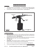
2. Prior to use, the Riveter requires the attachment of the Quick Connector (53) to its Air Cylinder (29). To do so, make sure the screen Air Filter is properly seated in the Air Cylinder. Wrap approximately 3” of pipe thread seal tape (not included) around the male threads of the Quick Connector. Then, firmly tighten the Quick Connector into the Air Cylinder. (See Figure B.) AIR CYLINDER (29) FIGURE B QUICK CONNECTOR (53) To Prime The Riveter: 1.
5. Insert the Piston Assembly (30 thru 33) back into the Air Cylinder (29). (See Figure C.) 6. Use the Spanner (36) to firmly screw the Cylinder Cap (33) back onto the Air Cylinder (29). (See Figure C.) AIR CYLINDER (29) SPANNER (36) PISTON ASSY.
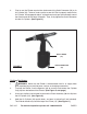
OPERATING INSTRUCTIONS Nosepieces: 1. The Riveter comes with four Nosepieces. The Nosepiece part numbers and sizes are as follows: (1A = 3/16”), (1B = 5/32”), (1C = 1/8”), (1D = 3/32”). (See Figure D.) 2. Use the Spanner (36) when changing Nosepieces. (See Figure D.) FRAME HEAD (11) SAFETY CAP (23) FRAME CAP NUT (22) FIGURE D NOSEPIECE (1A, 1B, 1C, 1D) TRIGGER (40) QUICK CONNECTOR (53) To Operate The Riveter: 1.
6. Insert the small end of a rivet fully through the Nosepiece (1A, 1B, 1C, or 1D). CAUTION! Make sure to NEVER to touch the Trigger (40) when you are inserting rivets. (See Figure D.) 7. Insert the rivet through the predrilled hole in the workpiece. 8. Hold the Riveter firmly with both hands, and squeeze the Trigger (40) to activate the Riveter. Repeat as necessary. Then, release pressure on the Trigger. (See Figure D.) 9. When finished using the Riveter, turn off the air compressor.
D. If you are going to clean the Jaws (7), use a steel brush and mild solvent. Then, apply a light coat of machine oil to the Jaws. If you are going to replace the Jaws, the entire assembly (6, 7, 8, 9, & 10) must be replaced at the same time, due to the possibility of additional parts being damaged when the Jaws were damaged. (See Assy. Diagram.) E. Insert the Jaws (7) back into the Jaw Case (6). (See Assy. Diagram.) F.
TROUBLESHOOTING Problem Possible Cause Worn or damaged Jaws. Jaws slipping. Jaws will not open. Likely Solution Replace Jaws. Loose Nosepiece. Tighten Nosepiece. Dir ty Jaws. Clean Jaws. Rivet pin not properly inser ted Make sure that Pin is fully inser ted. into Riveter. Stroke is too shor t. Weak pulling action. Leaking air. Low oil. Prime Riveter. Rivet wrong size. Use proper rivet length. Low air pressure. Check regulator. Broken/inadequate air compressor.
ASSEMBLY DIAGRAM 11 1A 6 7 8 10A 20 24 23 22 10 13 9 1214 14 37 15 16 38 40 43A 39 30-1 44 29 41 31A 33 35 36 44A 1B 1C 1D 43A 45B 43 30-5 30-3 32 19 24 30-4 30-2 23 26 25 1718 45 44 51 52 35 28 27 NOTE: Some parts are listed and shown for illustration purposes only, and are not available individually as replacement parts. PLEASE READ THE FOLLOWING CAREFULLY THE MANUFACTURER AND/OR DISTRIBUTOR HAS PROVIDED THE PARTS DIAGRAM IN THIS MANUAL AS A REFERENCE TOOL ONLY.