Table of Contents SAFETY Safety.......................................................... 2 Specifications.............................................. 6 Setup........................................................... 6 Operation..................................................... 8 Maintenance............................................... 12 Parts List and Diagram............................... 14 Warranty.....................................................
General Tool Safety Warnings (cont.) 0–6 18 16 16 14 6.1 – 10 18 16 14 12 10.1 – 12 16 16 14 12 12.1 – 16 14 12 Do not use. 9. USE PROPER EXTENSION CORD. Make sure your extension cord is in good condition. When using an extension cord, be sure to use one heavy enough to carry the current your product will draw. An undersized cord will cause a drop in line voltage resulting in loss of power and overheating.
Grounding Instructions SAFETY TO PREVENT ELECTRIC SHOCK AND DEATH FROM INCORRECT GROUNDING WIRE CONNECTION READ AND FOLLOW THESE INSTRUCTIONS: 110-120 V~ Grounded Tools: Tools with Three Prong Plugs 1. In the event of a malfunction or breakdown, grounding provides a path of least resistance for electric current to reduce the risk of electric shock. This tool is equipped with an electric cord having an equipment-grounding conductor and a grounding plug.
12. Maintain labels and nameplates on the tool. These carry important safety information. If unreadable or missing, contact Harbor Freight Tools for a replacement. 13. Avoid unintentional starting. Prepare to begin work before turning on the tool. 14. To prevent FIRE, do not install a larger bulb in this item′s bulb holder than listed in the specifications chart. 15. People with pacemakers should consult their physician(s) before use.
Specifications SAFETY Electrical Rating 120V~ / 60Hz / 2.4A Spindle Speeds 760, 1150, 1630, 2180, 3070 RPM 5 Speeds Table Tilt 45º left and right Swing 8" Spindle Stroke 2" Spindle Taper B16 Chuck Capacity 1/16″ - 1/2″ (13mm) Worklight Bulb Size E14 base, 120V, 15W 227541 Setup - Before Use: Read the ENTIRE IMPORTANT SAFETY INFORMATION section at the beginning of this manual including all text under subheadings therein before set up or use of this product.
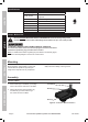
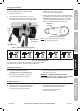
Table Support 1. Loosen the Pivot Lever (51). 3. Tighten the Pivot Lever to secure the Table Support in place. Table Support (52) Column (8) SAFETY 2. Slide the Table Support (52) over the Column (8). SETUP Pivot Lever (51) Figure B: Installing Table Support Headstock and Feed Handles 1. Loosen the two Set Screws (9) on the right side of the Headstock (42) so they will stay clear while installing it. Headstock (42) Set Screws (9) 3. Tighten the two Set Screws to secure the Headstock in place. 4.
Operating Instructions Read the ENTIRE IMPORTANT SAFETY INFORMATION section at the beginning of this manual including all text under subheadings therein before set up or use of this product. SAFETY Tool Set Up TO PREVENT SERIOUS INJURY FROM ACCIDENTAL OPERATION: Turn the Power Switch of the tool off and unplug the tool from its electrical outlet before performing any procedure in this section. TO PREVENT SERIOUS INJURY: DO NOT OPERATE WITH ANY GUARD DISABLED, DAMAGED, OR REMOVED.
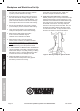
Changing Drill Speed 3. Consult the chart below and position the Belt (59) on the Pulleys (16, 60) according to the desired drill speed. 1. Open the pulley cover. 2. Loosen the Motor Tension Knob (10) on the Headstock (42), and move the Motor (14) towards the Headstock to relieve tension on the Belt (59). 4. When the Belt has been correctly positioned, tighten it by pushing the Motor away from the Headstock until the belt deflects by approximately 1/2″ at its center when using reasonable thumb pressure.
Workpiece and Work Area Set Up SAFETY 1. Designate a work area that is clean and well‑lit. The work area must not allow access by children or pets to prevent distraction and injury. 9. FOR SMALL MATERIALS that cannot be clamped to the table, use a drill press vise. Make sure the vise is clamped or bolted to the table. 2. Route the power cord along a safe route to reach the work area without creating a tripping hazard or exposing the power cord to possible damage.
1. Bring the drill bit down with the Feed Knob to where the hole is to be drilled. Make minor workpiece alignment adjustments. 2. Plug the Power Cord into an electrical outlet. 3. Turn the Drill Press on. 5. To prevent accidents, turn off the tool and disconnect its power supply after use. Clean, then store the tool indoors out of children’s reach. MAINTENANCE OPERATION SETUP 4. Pull down on the Feed Knob and slowly drill the hole into the workpiece.
Maintenance and Servicing Procedures not specifically explained in this manual must be performed only by a qualified technician. SAFETY TO PREVENT SERIOUS INJURY FROM ACCIDENTAL OPERATION: Turn the Power Switch of the tool off and unplug the tool from its electrical outlet before performing any procedure in this section. TO PREVENT SERIOUS INJURY FROM TOOL FAILURE: Do not use damaged equipment. If abnormal noise or vibration occurs, have the problem corrected before further use.
Troubleshooting Tool will not start. 1. Cord not connected. 2. No power at outlet. Tool operates slowly. 3. Tool’s thermal reset breaker tripped (if equipped). 4. Internal damage or wear. (Carbon brushes or switch, for example.) Extension cord too long or wire size too small. Performance 1. Accessory dull or damaged. decreases 2. Carbon brushes worn or damaged. over time. Excessive noise 1. Internal damage or wear. (Carbon or rattling. brushes or bearings, for example.) 2.
Parts List and Diagram PLEASE READ THE FOLLOWING CAREFULLY SAFETY THE MANUFACTURER AND/OR DISTRIBUTOR HAS PROVIDED THE PARTS LIST AND ASSEMBLY DIAGRAM IN THIS MANUAL AS A REFERENCE TOOL ONLY. NEITHER THE MANUFACTURER OR DISTRIBUTOR MAKES ANY REPRESENTATION OR WARRANTY OF ANY KIND TO THE BUYER THAT HE OR SHE IS QUALIFIED TO MAKE ANY REPAIRS TO THE PRODUCT, OR THAT HE OR SHE IS QUALIFIED TO REPLACE ANY PARTS OF THE PRODUCT.
Assembly Diagram 26 25 31 59 24 23 33 32 34 33 15 22 60 61 57 62 39 63 39 64 21 38 73 24 63 35 27 39 16 20 19 39 40 36 37 18 3 17 15 41 58 64 SAFETY 27 28 29 48 47 46 45 44 43 42 13 50 65 66 67 56 55 54 53 52 9 10 14 8 7 51 6 68 OPERATION 49 11 12 5 66 4 69 70 3 35 72 1 2 MAINTENANCE 71 SETUP 30 Item 60238 For technical questions, please call 1-800-444-3353.
Limited 90 Day Warranty Harbor Freight Tools Co. makes every effort to assure that its products meet high quality and durability standards, and warrants to the original purchaser that this product is free from defects in materials and workmanship for the period of 90 days from the date of purchase.