Table of Contents Safety.......................................................... 2 Maintenance............................................... 11 Setup........................................................... 6 Parts List and Diagram............................... 14 Specifications.............................................. 6 Warranty..................................................... 16 SAFETY Operation....................................................
IMPORTANT SAFETY INFORMATION WARNING Read all safety warnings and instructions. Failure to follow the warnings and instructions may result in electric shock, fire and/or serious injury. Save all warnings and instructions for future reference. The warnings, precautions, and instructions discussed in this instruction manual cannot cover all possible conditions and situations that may occur.
Air Compressor Safety Warnings SAFETY 1. Risk of fire or explosion - do not spray flammable liquid in a confined area or towards a hot surface. Spray area must be well‑ventilated. Do not smoke while spraying or spray where spark or flame is present. Arcing parts - keep compressor at least 20 feet away from explosive vapors, such as when spraying with a spray gun. 2. Risk of bursting - do not adjust regulator higher than marked maximum pressure of attachment. 3.
TO PREVENT ELECTRIC SHOCK AND DEATH FROM INCORRECT GROUNDING WIRE CONNECTION: Check with a qualified electrician if you are in doubt as to whether the outlet is properly grounded. Do not modify the power cord plug provided with the compressor. Never remove the grounding prong from the plug. Do not use the compressor if the power cord or plug is damaged. If damaged, have it repaired by a service facility before use.
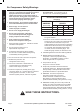
Specifications Model Electrical Rating 69666 120V~ / 60Hz / 13.5A 1/ ″ 4 SAFETY Air Outlet Size Air Pressure 69669 Shut-off Restart Air Tank Capacity Air Flow Capacity Sound Level -18 NPT 150 PSI 125 PSI 26 Gallons 17 Gallons 226892 4 SCFM @ 90 PSI 5 SCFM @ 40 PSI 91 dB @ 3′ Instructions for putting into use Read the ENTIRE IMPORTANT SAFETY INFORMATION section at the beginning of this manual including all text under subheadings therein before set up or use of this product.
1. Break in the new Air Compressor as follows: a. Turn the Power Switch off and unplug the unit. Insert a male coupler (sold separately) into the female Quick Coupler and fully open all regulators and valves. b. Plug in the Power Cord. c. Turn the Power Switch ON. d. Let the unit run for 30 minutes. Air will expel freely through the Coupler. e. Turn the Power Switch OFF. Note: An in-line shutoff ball valve is an important safety device because it controls the air supply even if the air hose is ruptured.
For technical questions, please call 1-800-444-3353.
Item 69666 69669 For technical questions, please call 1-800-444-3353.
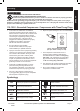
Operating Instructions Read the ENTIRE IMPORTANT SAFETY INFORMATION section at the beginning of this manual including all text under subheadings therein before set up or use of this product. SAFETY Compressor Area Set Up 1. Designate a work area that is clean and well‑lit. The work area must not allow access by children or pets to prevent injury. 2. Locate the Compressor on a flat level surface to ensure proper pump lubrication and to prevent damage to the unit.
Automatic Shut off System 2. Possible causes of repeated automatic shut off of the compressor are: a. Shut off all tools. a. Using an extension cord that is too long or narrow; b. Wait until the Compressor cools down (about 10 minutes); b. An air leak or open hose causing the compressor to cycle too often and build up heat. c. If the unit does not start up again on its own, move the Power Switch to OFF position, then back to ON; 3.
Draining Moisture from the Tank The Drain Valve is located under the Tank. It must be used daily to release all trapped air and moisture from the Tank. This will eliminate condensation which can cause tank corrosion. CAUTION! Do not open the Drain Valve so that more than four threads are showing. SAFETY 1. Turn the Power switch of the compressor off. 3. Unthread the Drain Valve two or three turns ONLY. 2. Place a collection pan under the Drain Valve. 4.
Troubleshooting (cont.) Likely Solutions 1. Air filters need cleaning/replacing. 1. Check inlet and outlet filters. Clean and/or replace as needed. 2. Unusually dusty environment. 2. Clean and/or replace filters more often or move unit to cleaner environment. 3. Extension cord used. 3. Eliminate extension cord. 4. Unit not on level surface. 4. Reposition unit on a level surface. 1. Loose fittings. 1.
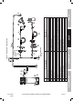
Parts List and Diagram Parts List SAFETY Part SETUP OPERATION MAINTENANCE 1 2 3 4 5 6 7 8 9 10 11 12 13 14 15 16 17 18 19 20 21 22 23 24 25 26 27 28 29 30 31 32 33 34 35 36 37 38 39 40 41 42 43 44 45 46 47 48 Description Bolt M6x35 Spring Washer M6 Cylinder Head Exhaust Elbow Valve Plate Inlet Valve Reed Outlet Valve Reed Limiter Inlet Valve Reed Cover Bolt M4x8 Spring Washer M4 Valve Plate Upper O-Ring Valve Plate Lower O-Ring Cylinder Bolt M6x16 Connecting Rod Cover Piston Ring Connecting Rod Nut M5
Assembly Diagram 1 94 2 SAFETY 3 12 35 36 37 7 9 10 13 15 6 42 23 22 41 55 56 57 58 2 24 20 21 26 44 40 22 27 45 43 39 32 50 5149 53 48 52 54 70 69 66 61 60 63 30 32 33 25 19 31 47 22 31 17 18 47 32 38 14 16 34 28 29 46 SETUP 5 4 59 65 75 74 67 73 68 71 72 90 64 95 62 93 76 78 92 77 91 80 MAINTENANCE 89 79 83 81 82 58 56 57 58 84 Item 69666 69669 85 86 88 56 87 For technical questions, please call 1-800-444-3353.
Limited 90 Day Warranty Harbor Freight Tools Co. makes every effort to assure that its products meet high quality and durability standards, and warrants to the original purchaser that this product is free from defects in materials and workmanship for the period of 90 days from the date of purchase.