30 Gallon, 180 PSI Gas Powered Two-Stage Air Compressor 67853 Air Compressor Using an engine indoors CAN KILL YOU IN MINUTES. Engine exhaust contains carbon monoxide. This is a poison you cannot see or smell. NEVER use inside a home or garage, EVEN IF doors and windows are open. Only use OUTSIDE and far away from windows, doors, and vents. When unpacking, make sure that the product is intact and undamaged. If any parts are missing or broken, please call 1-800-444-3353 as soon as possible.
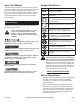
Save This Manual Symbol Definitions Keep this manual for the safety warnings and precautions, assembly, operating, inspection, maintenance and cleaning procedures. Write the product’s serial number in the back of the manual near the assembly diagram (or month and year of purchase if product has no number). Keep this manual and the receipt in a safe and dry place for future reference.
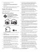
. Set up and use only on a flat, level, well‑ventilated surface. 5. Use only lubricants and fuel recommended in the engine manual or in the Specifications chart of this manual. 6. Wear ANSI-approved safety goggles, heavy-duty work gloves, and dust mask/respirator during set up. Engine Precautions Follow engine precautions and instructions in the included engine instruction manual. Operating Precautions Carbon Monoxide Hazard Using an engine indoors CAN KILL YOU IN MINUTES.
24. Keep hands and feet away from moving parts. Do not reach over or across equipment while operating. 25. Before use, check for misalignment or binding of moving parts, breakage of parts, and any other condition that may affect the equipment’s operation. If damaged, have the equipment serviced before using. Many accidents are caused by poorly maintained equipment. 26. Use the correct equipment for the application.
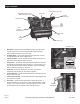
Engine Controls Pump Safety Valve (91) Belt Guard Frame (121) & Belt Guard Cover (129) Pilot Valve Air Filter Assembly (84) ON/OFF Switch Oil Sight Glass (19) Tank Pressure Gauge (97) Tank Safety Valve (98) Air Outlet (105) Drain Valve (137) Crankcase (16) 1. Belt Guard - The Belt Guard encloses the pulleys and drive belts. It protects the user from the moving parts and allows the large pulley to direct cooling air to the Air Pump. 2.
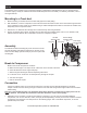
Set up The emission control system for this Compressor’s Engine is warranted for standards set by the U.S. Environmental Protection Agency and by the California Air Resources Board (also known as CARB). For warranty information, refer to the engine manual. Mounting to a Truck bed 1. Before mounting, if needed, reinforce the area with plywood or steel plating. 2. With assistance, move the compressor to the truck bed location and mark the floor of the truck bed through the holes in the compressor’s feet.
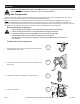
Page 6 A B C D E F G H For technical questions, please call 1-800-444 3353.
B A Item 67853 A B C D E F G H I J K L M N O Description F E F C C H H J I K J L Function L M M O N For noise and vibration reduction Secures air compressor in place Isolates sections of system for maintenance For vibration reduction Distributes air to branch lines To drain moisture from system Brings air to point of use Prevents dirt and condensation from damaging tool or work piece Prevents water vapor from damaging work piece Adjusts air pressure to tool For air tool lubrication Con
Operation Read the entire Important Safety Information section at the beginning of this manual including all text under subheadings therein before set up or use of this product. Using the Compressor Inspect Compressor, engine, pump and equipment looking for damaged, loose, and missing parts before set up and starting. If any problems are found, do not use equipment until fixed properly.
5. To start a cold engine, move the Choke to the CHOKE (start/ closed) position. To restart a warm engine, leave the Choke in the RUN position. 6. 5 For ELECTRIC START For MANUAL START A. Turn the Engine Switch to ON. Turn the Engine Switch to START. Note: To prolong starter life, use short starting cycles (5 seconds maximum). Then wait one minute before attempting to start again. ON ON OFF START B.
9. When the Gas Engine is started and running, the compressor Pump starts compressing air into the Air Tank. Open the in-line Shutoff Valve and adjust the Pressure Regulator (sold separately) so that the air output is enough to properly power the tool, but the output will not exceed the tool’s maximum air pressure at any time. Turn the knob clockwise to increase the pressure and counterclockwise to decrease pressure. Adjust the pressure gradually, while checking the air output gauge to set the pressure.
12. Close the in-line Shutoff Valve. 12 13. Bleed air from the tool then disconnect the tool. 13 14. Open the Drain Valve at the bottom of the Tank, to release any built-up moisture and the internal tank pressure. 14 15. Clean, then store the Air Compressor indoors. Item 67853 For technical questions, please call 1-800-444 3353.
Adding Oil Maintenance Crankcase (16) WARNING To prevent serious injury from accidental starting: Turn the Power Switch of the equipment to its “OFF” position, release tank air pressure, wait for the engine to cool, and disconnect the spark plug cap before performing any inspection, maintenance, or cleaning procedures. To prevent serious injury from equipment failure: Do not use damaged equipment. If abnormal noise, vibration, or excess smoking occurs, have the problem corrected before further use.
Maintenance Changing Oil Adjusting Belt Tension To drain the oil from the Pump Crankcase: a. Place a container under the Drain Plug. 1. Remove the Belt Guard Cover (129) and set it aside. Deflection Distance b. Remove the Oil Plug to allow air flow into the Pump. c. Remove the Drain Plug, allowing the oil to drain into the container. d. When the oil is completely drained from the Pump, replace the Drain Plug. e. Fill the Pump with new compressor oil to the FULL level on the Oil Sight Glass. f.
Troubleshooting Problem Engine will not start Possible Causes COMPRESSOR SPECIFIC: 1. Pilot Valve closed. (Note: See engine 2. manual for engine specific issues.) 1. Compressor overheats 2. Tank already pressurized. Incorrect lubrication or not enough lubrication. Worn parts. 1. Poor air outlet seal. 2. Loose cylinder/cylinder head. Severe air leakage 3. Damaged valve or housing. 4. Dirty, worn or damaged valve. 1. Low engine idle. Unit stalls Excessive noise Oil in the discharge air 2. 3. 4. 1.
PLEASE READ THE FOLLOWING CAREFULLY The manufacturer and/or distributor has provided the parts list and assembly diagram in this manual as a reference tool only. Neither the manufacturer or distributor makes any representation or warranty of any kind to the buyer that he or she is qualified to make any repairs to the product, or that he or she is qualified to replace any parts of the product.
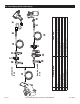
Pump Parts List Part 1 2 3 4 5 6 7 8 9 10 11 12 13 14 15 16 17 18 19 20 21 22 23 24 25 26 27 28 29 30 31 32 33 34 35 36 37 38 39 40 41 42 43 44 45 46 47 Page 16 Description Bolt M12×55 Spring Washer 12 Flat Washer Drive Pulley Oil Seal Circle Flange Plate O-ring φ85 Bearing Bolt M12×40 Oil Breather Crank Case End Cover Flat Key Crankshaft Bearing Gasket Crankcase Oil Plug Gasket Oil Sight Glass Drain Oil Bolt Second Stage Cylinder Head Bolt M12×40 Spring Washer 12 Gasket Connecting Rod A Connecting Rod
Pump Assembly Diagram Item 67853 For technical questions, please call 1-800-444 3353.
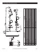
Tank Parts List Part 95 96 97 98 99 100 101 102 103 104 105 106 107 108 109 110 111 112 113 114 115 116 Page 18 Description Tank Connector Pressure Gauge Tank Safety Valve Unloader Valve Throttle Control Connector Taper Sleeve Pipe Nut Brass Tube Air Outlet Engine Bolt M10×40 Nut M10 Bracket Bolt M10×50 Nut M10 Washer 8 Bolt M8×20 Bottom Plate Nut M14 Spring Washer 14 Qty 1 1 1 1 1 1 1 2 2 1 1 1 4 4 1 4 4 1 1 1 1 1 Part 117 118 119 120 121 122 123 124 125 126 127 128 129 130 131 132 133 134 135 136 13
Tank Assembly Diagram Item 67853 For technical questions, please call 1-800-444 3353.
Limited 90 Day Warranty Harbor Freight Tools Co. makes every effort to assure that its products meet high quality and durability standards, and warrants to the original purchaser that this product is free from defects in materials and workmanship for the period of 90 days from the date of purchase.
Specifications Pump Two stage Air Outlet Size 1/2”- NPT female Air Pressure Auto Shut-Off @ 180 PSI Restart @ 140 PSI Air Tank Capacity 30 Gallons Air Flow Capacity 18 SCFM @ 90 PSI 19.5 SCFM @ 40 PSI Oil Capacity 61 oz. (1.
212, 346 and 420 cc Horizontal Engines 68120/68121 212cc Horizontal Engine 68136 346cc Horizontal Engine 68306 420cc Horizontal Engine Using an engine indoors CAN KILL YOU IN MINUTES. Engine exhaust contains carbon monoxide. This is a poison you cannot see or smell. NEVER use inside a home or garage, EVEN IF doors and windows are open. Only use OUTSIDE and far away from windows, doors, and vents. When unpacking, make sure that the product is intact and undamaged.
Specifications Description Displacement Engine Type Cooling System Fuel Engine Oil Type Capacity Type SAE Capacity Run Time @ 50% Load with full tank Sound Level at 22 feet Bore x Stroke Compression Ratio Rotation viewed from PTO 68120, 68121 Shaft Spark Plug Valve Clearance Speed Page 2 68306 212cc 346cc 420cc Horizontal Single Cylinder 4 stroke OHV Forced air cooled 87+ octane unleaded gasoline 1 Gallon 1 Gallon 1 Gallon 10W-30 above 32° F 5W30 at 32° F or below 0.5 Quart 1.16 Quart 1.
Save This Manual Symbol Definitions Keep this manual for the safety warnings and precautions, assembly, operating, inspection, maintenance and cleaning procedures. Write the product’s serial number in the back of the manual near the assembly diagram (or month and year of purchase if product has no number). Keep this manual and the receipt in a safe and dry place for future reference.
Set up Precautions 1. Gasoline fuel and fumes are flammable, and potentially explosive. Use proper fuel storage and handling procedures. Do not store fuel or other flammable materials nearby. 2. Have multiple ABC class fire extinguishers nearby. 3. Operation of this equipment may create sparks that can start fires around dry vegetation. A spark arrestor may be required. The operator should contact local fire agencies for laws or regulations relating to fire prevention requirements. 4.
23. Use the equipment, accessories, etc., in accordance with these instructions and in the manner intended for the particular type of equipment, taking into account the working conditions and the work to be performed. Use of the equipment for operations different from those intended could result in a hazardous situation. 4. Wear ANSI-approved safety goggles, heavy-duty work gloves, and dust mask/respirator during service. 24. Do not operate the equipment with known leaks in the engine’s fuel system. 6.
Engine Controls Air Filter Fuel Cap Engine Switch (Electric Start Models) Starter Handle Muffler Oil Drain Plug Dipstick Throttle Starter Choke Fuel Valve Serial Number Location (Write on front cover of manual.) Engine Switch (Manual Start Models) Page 6 For Engine technical questions, please call 1-800-520-0882.
Battery Setup Instructions Set Up Model 68120: The emission control system for this engine is warranted for standards set by the U.S. Environmental Protection Agency. For warranty information, refer to the last pages of this manual. Models 68306, 68121, and 68136: The emission control system for this Generator’s Engine is warranted for standards set by the U.S. Environmental Protection Agency and by the California Air Resources Board (also known as CARB).
Checking and Filling Fuel Operation Read the ENTIRE IMPORTANT SAFETY INFORMATION section at the beginning of this manual including all text under subheadings therein before set up or use of this product. Pre-Start Checks WARNING! TO PREVENT SERIOUS INJURY FROM FIRE: Fill the fuel tank in a well-ventilated area away from ignition sources. If the engine is hot from use, shut the engine off and wait for it to cool before adding fuel. Do not smoke. 1. Clean the Fuel Cap and the area around it. 2.
Manual Start 1. To start a cold engine, move the Choke to the CHOKE position. To restart a warm engine, leave the Choke in the RUN position. 1 CHOKE RUN 2. Open the Fuel Valve. 2 3. Slide the Throttle or Speed Control Lever to 1/3 away from the SLOW position (the “turtle”). Note: Some tools have a Speed Control Lever located elsewhere on the tool which functions the same as the Throttle. Use the Speed Control Lever in place of the Throttle when the tool is so equipped. 3 O 4.
6. Allow the Engine to run for several seconds. Then, if the Choke lever is in the CHOKE position, move the Choke Lever very slowly to its RUN position. 6 NOTE: Moving the Choke Lever too fast could stall the engine. CHOKE RUN IMPORTANT: Allow the engine to run at no load for five minutes with no load after each start‑up so that the engine can stabilize. 7. Adjust the Throttle as needed. 8. Break-in Period: a. Breaking-in the engine will help to ensure proper equipment and engine operation. b.
Electric Start (if equipped) 1. To start a cold engine, move the Choke to the CHOKE position. To restart a warm engine, leave the Choke in the RUN position. 1 CHOKE RUN 2 2. Open the Fuel Valve. 3. Slide the Throttle or Speed Control Lever to 1/3 away from the SLOW position (the “turtle”). Note: Some tools have a Speed Control Lever located elsewhere on the tool which functions the same as the Throttle. Use the Speed Control Lever in place of the Throttle when the tool is so equipped. 3 ON 4.
5. Allow the Engine to run for several seconds. Then, if the Choke lever is in the CHOKE position, move the Choke Lever very slowly to its RUN position. 5 NOTE: Moving the Choke Lever too fast could stall the engine. CHOKE RUN IMPORTANT: Allow the engine to run at no load for five minutes with no load after each start‑up so that the engine can stabilize. 6. Adjust the Throttle as needed. 7. Break-in Period: a. Breaking-in the engine will help to ensure proper equipment and engine operation. b.
Service WARNING TO PREVENT SERIOUS INJURY FROM ACCIDENTAL STARTING: Turn the Power Switch of the equipment to its “OFF” position, wait for the engine to cool, and disconnect the spark plug cap before performing any inspection, maintenance, or cleaning procedures. TO PREVENT SERIOUS INJURY FROM EQUIPMENT FAILURE: Do not use damaged equipment. If abnormal noise, vibration, or excess smoking occurs, have the problem corrected before further use. Follow all service instructions in this manual.
Checking and Filling Fuel WARNING! TO PREVENT SERIOUS INJURY FROM FIRE: Fill the fuel tank in a well-ventilated area away from ignition sources. If the engine is hot from use, shut the engine off and wait for it to cool before adding fuel. Do not smoke. 1. Clean the Fuel Cap and the area around it. 2. Unscrew and remove the Fuel Cap. 3. If needed, fill the Fuel Tank to about 1 inch under the fill neck of the Fuel Tank with 87 octane or higher unleaded gasoline.
Spark Plug Maintenance 2. FUEL: WARNING! TO PREVENT SERIOUS INJURY FROM FIRE: Drain the fuel tank in a well-ventilated area away from ignition sources. If the engine is hot from use, shut the engine off and wait for it to cool before draining fuel. Do not smoke. Spark Plug Cap a. Place a funnel leading to a proper gasoline container below the carburetor. 1. Disconnect spark plug cap from end of plug. Clean out debris from around spark plug. 2. Using a spark plug wrench, remove the spark plug. 3.
Troubleshooting Problem Possible Causes Engine will not start FUEL RELATED: 1. No fuel in tank or fuel valve closed. 2. Choke not in CHOKE position, cold engine. 3. Gasoline with more than 10% ethanol used. (E15, E20, E85, etc.) Probable Solutions 9. Clogged Fuel Filter. FUEL RELATED: 1. Fill fuel tank and open fuel valve. 2. Move Choke to CHOKE position. 3. Clean out ethanol rich gasoline from fuel system. Replace components damaged by ethanol. Use fresh 87+ octane unleaded gasoline only.
Problem Engine misfires Possible Causes 1. Spark plug cap loose. 2. Incorrect spark plug gap or damaged spark plug. 3. Defective spark plug cap. 4. Old or low quality gasoline. 5. Incorrect compression. Engine stops suddenly 1. Low oil shutdown. 2. Fuel tank empty or full of impure or low quality gasoline. 3. Defective fuel tank cap creating vacuum, preventing proper fuel flow. 4. Faulty magneto. 5. Disconnected or improperly connected spark plug cap. Probable Solutions 1. Check wire connections. 2.
Emission Control System Warranty Warranties Limited 90 Day Warranty Harbor Freight Tools Co. makes every effort to assure that its products meet high quality and durability standards, and warrants to the original purchaser that this product is free from defects in materials and workmanship for the period of 90 days from the date of purchase.
Harbor Freight Tools Emission Control Defects Warranty Coverage 4. Warranty claims shall be filed in accordance with the provisions of the HFT warranty policy explained in the box at the top of the previous page. HFT shall not be liable for any loss of use of the engine, for any alternative usage, for any damage to goods, loss of time, or inconvenience.
68120 212cc Parts List and Diagram Part 1 2 3 4 5 6 7 8 9 10 11 12 13 14 15 16 17 18 19 20 21 22 23 24 25 26 27 28 29 30 31 32 33 34 35 36 37 38 39 40 41 42 43 44 45 46 47 48 49 50 Page 20 Description Gasket, Cylinder Head Cover Asm., Cylinder Head Gasket, Cylinder Head Cover Tube, Breather Bolt Stud Stud Stud Pin Bolt, Cylinder Head Plug, Spark Head Asm., Cylinder Crankcase Asm. Sensor, Engine Oil Gear Asm.
Horizontal Engines 5 5 5 5 2 3 76 76 4 10 10 10 10 11 12 8 75 8 71 70 6 77 69 7 1 67 9 9 31 31 33 31 30 37 38 39 31 31 31 24 34 26 33 53 52 53 52 35 25 51 51 36 27 47 28 47 68 49 43 5446 44 54 41 48 48 50 50 45 28 29 42 40 23 14 93 74 23 32 93 15 92 95 19 96 17 94 97 98 72 72 73 18 16 22 99 21 13 84 91 20 83 82 81 90 90 82 85 89 18 17 85 78 62 88 62 87 86 79 59 58 80 64 55 66 65 60 57 63 5
68121 212cc Parts List and Diagram Part 1 2 3 4 5 6 7 8 9 10 11 12 13 14 15 16 17 18 19 20 21 22 23 24 25 26 27 28 29 30 31 32 33 34 35 36 37 38 39 40 41 42 43 44 45 46 47 48 49 50 51 52 53 54 Page 22 Description Gasket, Cylinder Head Cover Asm., Cylinder Head Gasket, Cylinder Head Cover Tube, Breather Bolt Stud Stud Stud Pin Bolt, Cylinder Head Plug, Spark Head Asm., Cylinder Crankcase Asm. Sensor, Engine Oil Gear Asm.
Horizontal Engines 5 5 5 5 2 3 76 76 4 10 10 10 10 78 79 11 80 78 12 8 8 75 71 70 6 69 31 7 1 67 9 9 31 31 33 31 30 37 38 39 77 31 31 24 34 26 33 53 52 53 52 35 25 51 51 36 27 47 28 47 68 49 43 5446 44 54 41 48 48 50 50 45 28 29 42 40 23 74 23 32 14 102 102 15 72 17 19 For Engine technical questions, please call 1-800-520-0882.
68136 346cc Parts List and Diagram Part 1 2 3 4 5 6 7 8 9 10 11 12 13 14 15 16 17 18 19 20 21 22 23 24 25 26 27 28 29 30 31 32 33 34 35 36 37 38 39 40 41 42 43 44 45 46 47 48 49 50 51 52 53 54 55 56 Page 24 Description Gasket, Cylinder Head Cover Asm., Cylinder Head Gasket, Cylinder Head Cover Tube, Breather Bolt Asm., Cylinder Head Cover Stud Stud Pin Bolt, Cylinder Head Plug, Spark Head Asm., Cylinder Crankcase Asm.
Horizontal Engines 5 84 84 82 83 80 80 2 78 78 78 3 79 34 81 34 34 34 4 31 61 34 34 34 61 60 59 51 60 53 52 37 59 62 29 58 62 58 63 54 73 57 10 72 9 9 9 43 9 70 74 42 36 46 47 41 38 35 32 7 45 30 11 7 44 33 42 6 71 33 48 6 1 26 14 8 26 39 8 40 49 25 56 56 50 25 90 88 55 15 55 25 92 20 25 89 92 77 91 89 19 93 94 85 89 86 87 89 75 28 95 89 97 For Engine technical questions, please call 1-800-520-0882.
68306 420cc Parts List and Diagram Part 1 2 3 4 5 6 7 8 9 10 11 12 13 14 15 16 17 18 19 20 21 22 23 24 25 26 27 28 29 30 31 32 33 34 35 36 37 38 39 40 41 42 43 44 45 46 47 48 49 50 51 52 53 54 55 56 57 58 59 60 61 Page 26 Description Gasket, Cylinder Head Cover Asm., Cylinder Head Gasket, Cylinder Head Cover Tube, Breather Bolt Asm., Cylinder Head Cover Stud Stud Pin Bolt, Cylinder Head Plug, Spark Head Asm., Cylinder Crankcase Asm.
Horizontal Engines 5 84 84 82 83 80 80 2 78 78 3 79 81 34 34 4 31 61 34 34 34 34 34 61 60 60 59 51 53 52 29 62 59 62 37 58 58 63 38 54 73 57 72 10 9 9 70 16 43 9 9 74 42 36 46 47 41 35 32 7 45 30 11 7 44 33 42 33 71 6 48 6 1 26 26 8 14 39 8 49 40 56 56 50 25 88 55 77 55 92 19 25 91 89 89 25 20 15 25 90 93 28 92 89 94 85 86 12 95 For Engine technical questions, please call 1-800-520-0882.
Mounting Hole Diagrams Note: Not to scale. ITEM 68120 / 68121 212cc 6.38 in. / 162mm 2.6 in. / 66mm 3.17 in. / 80.5mm 2.97 in. / 75.5mm 1.6 in. / 40.5mm ITEM 68136 346cc and ITEM 68306 420cc 7.72 in. / 196mm 4.13 in. / 105mm 3.39 in. / 86mm For Engine technical questions, please call 1-800-520-0882. 4.06 in.
Power Take-Off Diagrams Note: Not to scale. ITEM 68120 / 68121 212cc 2.43 in. / 61.7mm 5/16-24UNF 0.67 in. / 17mm Ø0.75 in. / 19.05mm 0.64 in. / 16.36mm 0.1875 in. / 4.78mm 5/16-24UNF 1.79 in. / 45.5mm Ø3.625 in. / 92mm 4.17 in. / 106mm 4x5/16-24UNF ITEM 68136 346cc and ITEM 68306 420cc Ø3.625 in. / 92mm (30°) (30°) 3.48 in. / 88.5mm 0.25 in. / 6.35mm Ø5.75 in. / 146mm Ø5 in. / 127mm Ø1 in. / 25.4mm Ø1.17 in. / 29.7mm 0.36 in. / 9.13mm 3/8-24UNF Ø6.5 in. / 165.1mm 1.1 in. / 28mm 2.
3491 Mission Oaks Blvd. • PO Box 6009 • Camarillo, CA 93011 • (800) 520-0882 www.harborfreight.