Specifications Rated Capacity 300 lb Maximum Lift Height 25" Axle Width 36" – 51" Patent Pending Safety Safety IMPORTANT SAFETY INFORMATION Failure to heed these warnings may result in personal injury and/or property damage: Assembly Precautions 1. Assemble only according to these instructions. Improper assembly can create hazards. 2. Wear ANSI-approved safety goggles and heavy-duty work gloves during assembly. 3. Keep assembly area clean and well lit. 4.
Assembly Instructions Read the ENTIRE IMPORTANT SAFETY INFORMATION section at the beginning of this document including all text under subheadings therein before set up or use of this product. Safety Safety 1. Place Lift Arm / Shaft Assembly flat on a horizontal surface. Move the two Safety Lock Levers (15) to the unlocked position as shown. Raise the Lift Arm portion of the assembly to an upright position.
3. Place the Lift Arm / Shaft Assembly onto the wheeled end of the Base (1) as shown and align the bolt holes. Secure the Lift Arm / Shaft Assembly to the Base using two Bolts (10), Lock Washers (9), and Nuts (8). Safety Safety Lift Arm / Shaft Assembly Nut (8) Lock Washer (9) Assembly Assembly Base (1) Bolt (10) Step 3: Connect Lift Arm / Shaft Assembly to Base 4. Insert Extension Beam (33) through the bracket on the Upper Lift Arm (29). Insert Extension Beam Pin (34) through center of bracket.
. Slide one Wheel Bracket (38) over each end of the Extension Beam (33). Width Pin (32) Wheel Bracket (38) Width Pin (32) Assembly Assembly Wheel Bracket (38) Safety Safety Insert Width Pins (32) to secure them in place. Extension Beam (33) Step 5: Install Wheel Brackets 6. Remove the R-Clip (36) and Washer (35) from one end of each Wheel Bracket Rod (37). Operation Operation Insert one Wheel Bracket Rod through the slots on each Wheel Bracket (38).
7. Insert the Foot Pedal (23) into its holder on the Ram (21). Secure the Foot Pedal in place using the Lock Washer (39) and Foot Pedal Bolt (22) through the side of its holder. Foot Pedal (23) Safety Safety Foot Pedal Bolt (22) Lock Washer (39) Assembly Assembly Step 7: Install Foot Pedal 8. Insert the Handle (27) into the bracket on the Lift Arm / Shaft Assembly and align the holes. Secure in place using the Handle Bolt (12) and Washer (13).
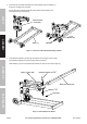
Handle Width Pin Safety Safety Components Wheel Bracket Assembly Assembly Width Pin Operation Operation Foot Pedal Safety Lock Lever Fluid Fill Hole Release Pedal Fluid Fill Plug Maintenance Maintenance Ram Tie-Down Bolt (remove before use) Safety Lock Levers in LOCKED position. Item 61523 Safety Lock Levers in UNLOCKED position. For technical questions, please call 1-800-444-3353.
Operating Instructions Read the entire Important Safety Information section at the beginning of this document including all text under subheadings therein before set up or use of this product. Safety Safety Bleeding IMPORTANT! Before first use, check for proper hydraulic fluid level in the Ram. Then thoroughly test the Jack for proper operation prior to its actual use. If the Jack appears not to be working properly, it may be necessary to bleed its hydraulic system of excess air. 1.
Maintenance and Servicing Safety Safety Procedures not specifically explained in this manual must be performed only by a qualified technician. TO PREVENT SERIOUS INJURY FROM ACCIDENTAL OPERATION: Do not use damaged equipment. If abnormal noise or vibration occurs, have the problem corrected before further use. Cleaning, Maintenance, and Lubrication 1. BEFORE EACH USE, inspect the general condition of the Jack. Check for: 3. Change the hydraulic fluid at least once every three years: a.
Parts List and Diagram PLEASE READ THE FOLLOWING CAREFULLY Safety Safety THE MANUFACTURER AND/OR DISTRIBUTOR HAS PROVIDED THE PARTS LIST AND ASSEMBLY DIAGRAM IN THIS MANUAL AS A REFERENCE TOOL ONLY. NEITHER THE MANUFACTURER OR DISTRIBUTOR MAKES ANY REPRESENTATION OR WARRANTY OF ANY KIND TO THE BUYER THAT HE OR SHE IS QUALIFIED TO MAKE ANY REPAIRS TO THE PRODUCT, OR THAT HE OR SHE IS QUALIFIED TO REPLACE ANY PARTS OF THE PRODUCT.
Maintenance Maintenance Operation Operation Assembly Assembly Safety Safety Assembly Diagram Item 61523 For technical questions, please call 1-800-444-3353.
Limited 90 Day Warranty Harbor Freight Tools Co. makes every effort to assure that its products meet high quality and durability standards, and warrants to the original purchaser that this product is free from defects in materials and workmanship for the period of 90 days from the date of purchase.