
Product manual
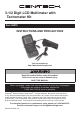

Page 10 For technical questions, please call 1-800-444-3353. SKU 95670
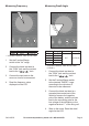
Measuring Resistance
Range Resolution Accuracy
200Ω 0.1Ω ±(1.0%+5)
2kΩ 1Ω
±(0.8%+5)
20kΩ 10Ω
200kΩ 100Ω
2MΩ 1kΩ
20MΩ 10kΩ ±(2.0%+7)
• Open Circuit Voltage: Less than 2.8V
• Overload Protection: 250V DC/AC RMS
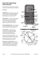
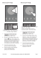
1. Connect the red test lead to the
“ ” Jack and the black
test lead to the “COM” Jack.
2. Set the Function/Range switch
to the desired Ω range.
3. Connect the test leads to the
resistor to be measured and read
the value displayed on the LCD.
Note: For resistance above 1MΩ, the
meter may take a few seconds to stabilize
reading. This is normal for high resistance
measuring.
Before measuring in-circuit
resistance, be sure the circuit under
test has all power removed and all
capacitors are fully discharged.
Note: The 200 and 2K resistance
modes offer additional features: a
Diode Test and Continuity Test. See
the following sections for details.
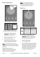
Diode Test
Range Description Test Condition
The approximate
forward voltage
of the diode
under test will
be displayed
on the LCD.
The forward
DC current is
approx. 1mA,
the reversed
DC voltage is
approx. 3V.
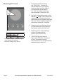
1. Connect the red test lead to the
“ ” Jack and the black test
lead to the “COM” Jack. The polarity
of the red test lead is positive “+”.
2. Set the Function/Range
switch to “ ” range.
3. Connect the red test lead to the anode
of the diode to be tested and the black
test lead to the cathode of the diode.
The approximate forward voltage drop
of the diode will be displayed on the
LCD. If the connection is reversed,
only gure “1” will be shown.