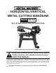
horizontal/vertical metal cutting bandsaw Model 93762 Set up and Operating Instructions Visit our website at: http://www.harborfreight.com Read this material before using this product. Failure to do so can result in serious injury. Save this manual. Copyright© 2006 by Harbor Freight Tools®. All rights reserved. No portion of this manual or any artwork contained herein may be reproduced in any shape or form without the express written consent of Harbor Freight Tools.
Contents Important SAFETY Information............................ 3 General Tool Safety Warnings...................................... 3 Band Saw Safety Warnings..... 5 Vibration Safety.................... 7 Grounding Instructions..... 7 Grounded Tools: Tools with Three Prong Plugs....... 7 Double Insulated Tools: Tools with Two Prong Plugs............................................. 8 SPECIFICATIONS.......................... 9 UNPACKING.................................. 9 ASSEMBLY INSTRUCTIONS........
NOTICE is used to address practices not related to personal injury. Save This Manual Keep this manual for the safety warnings and precautions, assembly, operating, inspection, maintenance and cleaning procedures. Write the product’s serial number in the back of the manual near the assembly diagram (or month and year of purchase if product has no number). Keep this manual and the receipt in a safe and dry place for future reference.
7. 8. DON’T FORCE TOOL. It will do the job better and safer at the rate for which it was designed. USE RIGHT TOOL. Don’t force tool or attachment to do a job for which it was not designed. RECOMMENDED MINIMUM WIRE GAUGE FOR EXTENSION CORDS (120 VOLT) NAMEPLATE AMPERES (at full load) EXTENSION CORD LENGTH 25’ 50’ 100’ 150’ 0–6 18 16 16 14 6.1 – 10 18 16 14 12 10.1 – 12 16 16 14 12 12.1 – 16 14 12 Do not use. TABLE A 9. USE PROPER EXTENSION CORD.
or other part that is damaged should be properly repaired or replaced. 20. DIRECTION OF FEED. Feed work into a blade or cutter against the direction of rotation of the blade or cutter only. 21. NEVER LEAVE TOOL RUNNING UNATTENDED. TURN POWER OFF. Don’t leave tool until it comes to a complete stop. Band Saw Safety Warnings For Your Own Safety Read Instruction Manual Before Operating Saw 1. Wear eye protection. 2. Do not remove jammed cutoff pieces until blade has stopped. 3.
19. Keep all safety guards in place and in proper working order. 20. Use indoors only. 21. If the teeth of the Saw Blade are so far apart that they straddle the workpiece, severe damage to the workpiece and/or Saw Blade will result. 22. The use of accessories or attachments not recommended by the manufacturer may result in a risk of injury to persons. 23. When servicing use only identical replacement parts. 24. Only use safety equipment that has been approved by an appropriate standards agency.
ditions and situations that may occur. It must be understood by the operator that common sense and caution are factors which cannot be built into this product, but must be supplied by the operator. Vibration Safety This tool vibrates during use. Repeated or long-term exposure to vibration may cause temporary or permanent physical injury, particularly to the hands, arms and shoulders. To reduce the risk of vibration-related injury: 1.
3. Improper connection of the equipment-grounding conductor can result in a risk of electric shock. The conductor with insulation having an outer surface that is green with or without yellow stripes is the equipment-grounding conductor. If repair or replacement of the electric cord or plug is necessary, do not connect the equipment-grounding conductor to a live terminal. 4.
SPECIFICATIONS Motor Cutting Capacity Speeds Throat Depth Angle Cutting Capacity Blade Horizontal Bed Vertical Bed V-Belt Type 120 V~ / 60 Hz / 1 HP / n01700/min 4-1/2” Round Stock / 4” x 6” Rectangular Stock 80 FPM / 120 FPM / 200 FPM 4-1/2” 0° ~ 55° (Left) Miter Plate on Horizontal Cutting Bed 64” L x 15/32” W x 0.
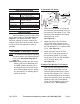
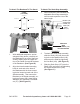
To Attach The Bandsaw To The Stand: STAND (TOP VIEW) To Attach The Stock Stop Assembly: 1. MOUNTING HOLE MOUNTING HOLE MOUNTING HOLE When mounted to the Bandsaw, the adjustable Stock Stop assembly is used to make repetitive cuts of the same length. HEX BOLT (149) SOCKET HEAD SCREW (156) MOUNTING HOLE SHAFT (158) STOCK STOP (157) MOUNTING HOLE MOUNTING HOLE END VIEW WITH HAND WHEEL (171) IN FOREGROUND SCREW (59) SPRING WASHER (58) FLAT WASHER (57) FIGURE C FIGURE B 1. 2.
To Attach The Pulley Cover: 2. PULLEY COVER (72) WORM SHAFT (9) HEX BOLT (76) FLAT WASHER (77) BODY FRAME (60) MOTOR SHAFT (81) Insert the Shaft Key (80) in the slot on the Motor Shaft (81). Align the slot in the Motor Pulley (79) with the Shaft Key. Slide the Motor Pulley fully onto the Motor Shaft. Then secure the Motor Pulley to the Motor Shaft, using one Socket Head Screw (2). (See Figure E.
Material Tool Steel, Stainless Alloy Steels, Bearing Bronze Speed (FPM) Pulley Groove Spindle Motor 80 Large Small Medium to High Carbon Steels, Hard Brass or Bronze 120 Medium Medium Low to Medium Carbon Steels, Soft Brass, Aluminum, Plastic 200 2. Small To Convert The Bandsaw For Vertical Use: NOTE: Notching, slitting, and contour work is best done with the Bandsaw in its vertical position.
SMALL VERTICAL CUTTING PLATE (194) SCREW (190) VERTICAL CUTTING PLATE (189) SCREW (190) FLAT WASHER (192) NUT (193) VERTICAL CUTTING PLATE SUPPORT (191) HEX HEAD BOLT (61) VERTICAL CUTTING PLATE (189) SCREW (190) FIGURE I 2. Remove the two Screws (190), and remove the Small Vertical Cutting Plate (194). (See Figure I.) 3. Guide the Saw Blade (82) through the slot in the Vertical Cutting Plate (189), and secure it in position with the two Screws (190). (See Figure I.) SKU 93762 FIGURE J 4.
OPERATING INSTRUCTIONS CAUTION! Turn the Power Switch (164) to its “OFF” position and unplug the tool from its electrical outlet prior to making adjustments to the tool. To Use The Vise: 1. Raise the Body Frame (60) to its vertical position, and lock the Body Frame in place with the Support Plate (150) and Locking Pin (153). (See Figure H.) MOVEABLE VISE PLATE (141) HAND WHEEL (171) 4. Clamp the workpiece firmly with the Moveable Vise Plate (141) by rotating the Hand Wheel (171) clockwise. (See Figure K.
Adjustments OUTER BLADE GUIDE BEARING (92, 104) To Adjust The Stock Stop: SAW BLADE (82) NUT (86, 96) (NOT SHOWN) WORKPIECE (NOT INCLUDED) SHAFT (91, 103) SHAFT (91, 103) STOCK STOP (157) SOCKET HEAD SCREW (156) FIGURE N 2. If a new Saw Blade does not correct the problem, check the Blade Adjustable Seats (83, 110) to obtain the proper clearance. (See Figure N.) 3. There should be from .000” (just touching) to .001” clearance between the Saw Blade and Blade Guide Bearings (88, 92, 100, 104).
ing the Locking Pin (153). (See Figure H.) 2. 3. Turn on the Bandsaw. The Saw Blade (82) is tracking properly when the back of the Blade is just touching the edge of the Blade Wheel (37) flange. The back of the Blade should not be rubbing against the flange. (See Figure P.) If adjustment is necessary, the Blade Guide Bearings (88, 92, 100, 104) should be clear of the Saw Blade (82). (See Figure N.) BLADE WHEEL (37) ing the Blade Tension Adjusting Knob (34). (See Figure O.) 6.
2. When the Bandsaw is not in use over long periods of time, release the tension on the Saw Blade (82). Adjusting The Blade Guide Brackets: GUIDE ADJUSTING KNOB (45) Adjusting The Feed Rate: BLADE GUIDE BRACKETS (90, 102) HANDLE (127) FIGURE Q The feed rate of the Body Frame (60) can be adjusted by turning the Handle (127) clockwise to decrease the feed rate or counterclockwise to increase the feed rate. Do not turn the Handle more than one turn at a time.
position. Never attempt to cut pipes or other round objects with the Bandsaw in its vertical position. Basic Bandsaw Operation -Vertical Position: 1. WARNING! Always wear ANSIapproved safety impact eye goggles when operating the Bandsaw. 2. Do not plug the Power Cord Plug into an electrical outlet until all necessary adjustments (as previously discussed in this manual) have been made.
from its electrical outlet. (See Figure S.) 15. Wait until the Saw Blade (82) comes to a complete stop. Then, remove the workpiece and scrap material from the Vertical Cutting Plate (189). (See Figure S.) 16. Remove the Locking Pin (153) and turn the Support Plate (150) to the left. Then, lower the Body Frame (60) to its horizontal position. (See Figure S.) 4. Secure the workpiece in the Vise assembly (138, 141). When cutting a large workpiece, make sure its entire length is properly supported.
Blade into the workpiece. (See Figure T.) 10. WARNING! Keep hands and fingers safely away from the cutting area. 11. Slowly lower the Body Frame (60), while it gradually feeds the Saw Blade (82) into the workpiece. Do not force the Bandsaw to remove material faster than it is designed to cut. (See Figure T.) 12. Never attempt to remove material stuck in the moving parts of the Bandsaw while it is plugged in and running. Turn off the Bandsaw if the workpiece is to be backed out of an uncompleted cut. 15.
INSPECTION, MAINTENANCE, AND CLEANING 1. 2. 3. WARNING! Make sure the Power Switch (164) is in its “OFF” position and the tool is unplugged from its electrical outlet before performing any inspection, maintenance, or cleaning procedures. Before each use, inspect the general condition of the Bandsaw. Check for loose screws, misalignment or binding of moving parts, cracked or broken parts, damaged electrical wiring, and any other condition that may affect its safe operation.
e. Place the new Saw Blade (82) between each of the Guide assemblies and around the Upper Blade Wheel (37) and Lower Blade Wheel (54). IMPORTANT: The teeth must be pointing downward toward the Motor. (See Figure U.) f. NOTE: The Bandsaw is equipped with a 64” diameter, .025” thick, 15/32” wide, 14 teeth per inch Saw Blade (82). The machine will also accept Blades in 4, 6, 8, and 10 tooth sizes. The choice of Blade pitch is determined by the thickness of the material to be cut.
5. To lubricate the Worm Gear and Worm Shaft: The Worm Gear (17) and Gear Shaft (19) run in an oil bath Gear Box and should not require an oil change more than once a year, unless the oil becomes contaminated or a leak occurs due to improper replacement of the Gear Box Cover (14). To change oil in the Gear Box: a. Position the Body Frame (60) in the horizontal position. (See Figure S.) 6.
TROUBLESHOOTING SKU 93762 For technical questions, please call 1-800-444-3353.
PARTS LIST Part # Qty Part # 1 Spindle Pulley Description 1 42 Washer Description Qty 1 2 Socket Head Screw(M8x8) 1 43 Flat Washer(5) 1 3 Screw(M4x8) 1 44 Socket Head Screw(M5x15) 1 4 Flat Washer(4) 1 45 Switch Push-Off Tip 1 5 Flat Washer(5) 1 46 Flat Washer(6) 1 6 Screw(M4x8) 2 47 Spring Washer(6) 1 7 Seal Cover 1 48 Screw(M6x14) 1 8 Oil Seal(B15x35x7) 1 49 Adjusting Knob 1 9 Bearing(6202Z) 1 50 Flat Washer 1 10 Spacer 1 51 Spacer 1 11 Bear
PARTS LIST (CONT.
PARTS LIST (CONT.) Part # Description Qty Part # Description Qty 163 Shaft 1 180 Handle Wheel 1 164 Cable Protector 1 181 Pin(2.5) 2 165 Switch Panel 1 182 Pull Handle 1 1 183 Stand 2 166 Screw(M3.
ASSEMBLY DIAGRAM 194: Vertical Cutting Plate Support Not Shown. NOTE: Some parts are listed and shown for illustration purposes only, and are not available individually as replacement parts. SKU 93762 For technical questions, please call 1-800-444-3353.
Limited 1 year / 90 Day warranty Harbor Freight Tools Co. makes every effort to assure that its products meet high quality and durability standards, and warrants to the original purchaser that for a period of ninety days from date of purchase that the engine/motor, the belts (if so equipped), and the blades (if so equipped) are free of defects in materials and workmanship.