
Cordless Saw - Bandsaw User Manual


SKU 93762 For technical questions, please call 1-800-444-3353. Page 9
SPECIFICATIONS
Motor 120 V~ / 60 Hz / 1 HP / n
0
1700/min
Cutting Capacity 4-1/2” Round Stock /
4” x 6” Rectangular Stock
Speeds 80 FPM / 120 FPM / 200 FPM
Throat Depth 4-1/2”
Angle Cutting
Capacity
0° ~ 55° (Left) Miter Plate on
Horizontal Cutting Bed
Blade 64” L x 15/32” W x 0.025” Thick /
14 TPI
Horizontal Bed 11-1/2” L x 7-1/2” W x 23-1/2” Height
Vertical Bed 9-5/8” L x 9-1/2” W x 33-1/2” Height
V-Belt Type 0-506
UNPACKING
When unpacking, check to make sure
all the parts shown on the Parts Lists on
pages 31 and 32 are included. If any
parts are missing or broken, please call
Harbor Freight Tools at the number shown
on the cover of this manual as soon as
possible.
ASSEMBLY INSTRUCTIONS
Note: For additional information regarding
the parts listed in the following pages,
refer to the Assembly Diagram on
page 33.
CAUTION! Always make sure the Power
Switch (164) for the Bandsaw is in
its “OFF” position and the tool is
unplugged from its electrical outlet
prior to assembling the tool, adding
any accessories, or making adjust-
ments to the tool.
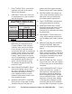
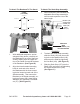
To Assemble The Stand:
PULL
HANDLE
(173)
TOOL PLATE
(175)
STAND
(174)
STAND
(174)
FLAT WASHER
(177)
SCREW
(178)
NUT
(176)
PIN
(172)
FLAT WASHER
(180)
NUT
(181)
HEX BOLT (183)
FLAT
WASHER
(184)
SPRING WASHER (185)
PIN
(188)
WHEEL SHAFT
(187)
WHEEL (182)
WHEEL
BRACKET
(186)
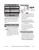
FIGURE A
1. Insert the Pull Handle (173) into the
two mounting holes located in the up-
per section of one Stand (174). Then
secure the Pull Handle to the Stand,
using two Pins (172).
(See Figure A.)
Attach one end of the Tool Plate 2.
(175) to the upper section of one
Stand (174), using two Screws (178),
two Flat Washers (177), and two Nuts
(176). (See Figure A.)
Attach the other end of the Tool 3.
Plate (175) to the upper section of
the remaining Stand (174), using
two Screws (178), two Flat Washers
(177), and two Nuts (176).
(See Figure A.)
To Attach The Wheels To The Stand:
Align the two mounting holes in the
Wheel Bracket (186) with the two
mounting holes located in the lower
section of the Stand (174). Then se-
cure the Wheel Bracket to the Stand,
using two Hex Bolts (183), two Spring
Washers (185), two Flat Washers
(184), two Flat Washers (180), and
two Nuts (181). (See Figure A.)