WARNING SYMBOLS AND DEFINITIONS This is the safety alert symbol. It is used to alert you to potential personal injury hazards. Obey all safety messages that follow this symbol to avoid possible injury or death. Safety Indicates a hazardous situation which, if not avoided, will result in death or serious injury. Indicates a hazardous situation which, if not avoided, could result in death or serious injury. Indicates a hazardous situation which, if not avoided, could result in minor or moderate injury.
Safety 14. The warnings, precautions, and instructions discussed in this instruction manual cannot cover all possible conditions and situations that may occur. It must be understood by the operator that common sense and caution are factors which cannot be built into this product, but must be supplied by the operator. Maintenance Operation Setup Save these instructions. Item 69465 For technical questions, please call 1-800-444-3353.
Specifications Safety Measurement Range -36ºF to 968ºF (-38ºC to 520ºC) Accuracy ± 2% above 32ºF ± 4.5% below 31ºF Response Time 1 Sec Spot Size Ratio 8:1 (Distance : Spot size) Needed Batteries Two AAA (not included) laSER liGht aVOiD DiRECt EYE EXPOSuRE max. Output: <1 mW, Wavelength: 635-660 nm CLASS II LASeR PRODuCT WaRninG to prevent serious injury, do not use for medical purposes. This product complies with 21 CFR 1040.10 and 1040.11 - Diode Mfr.
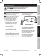
Operating Instructions Safety Read the entire Important Safety Information section at the beginning of this manual including all text under subheadings therein before set up or use of this product. General Operating Instructions 2. Push the ºF/ºC button to toggle between Fahrenheit to Celsius, and to recover the last reading when in OFF mode. 3. Squeeze the Trigger and move the laser to see a constant temperature reading and max reading. 4.
Maintenance and Servicing Safety Procedures not specifically explained in this manual must be performed only by a qualified technician. To prevent serious injury from accidental operation: Release the Trigger and remove the batteries from the Laser Thermometer before performing any inspection, maintenance, or cleaning procedures. To prevent serious injury from tool failure: Do not use damaged equipment. If damage is noted, have the problem corrected before further use.
Parts List and Diagram Description Front Cover Rear Cover Battery Cover Trigger °F/°C Button LCD Back Light Layered Block PCB Switch Part 11 12 13 14 15 16 17 18 19 20 Description Front Mass Lens RMASS TPI RMASS Thermopile Laser Holder -B Laser Module Negative Plate Positive Plate P-N Plate Part 21 22 23 24 25 26 Description Tapping Screw (M 1.7*5L) Machine Screw (M 2* 4L) Tapping Screw (M 1.7*4L) Tapping Screw (M 2.
Limited 90 Day Warranty Harbor Freight Tools Co. makes every effort to assure that its products meet high quality and durability standards, and warrants to the original purchaser that this product is free from defects in materials and workmanship for the period of 90 days from the date of purchase.