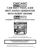
7,500 Watt Peak, 6,600 Watt Rated GENERATOR WITH ROBIN® ENGINE 91377 ASSEMBLY AND OPERATING INSTRUCTIONS Distributed exclusively by Harbor Freight Tools. 3491 Mission Oaks Blvd., Camarillo, CA 93011 Visit our Web site at http://www.harborfreight.com To Help prevent serious injury OR Death, Read and understand all warnings and instructions before use. Copyright © 2004 by Harbor Freight Tools®. All rights reserved.
Specifications Generator Engine Frame Estimated Run Time Overall Dimensions Suggested Oil Wattage @ 240V: 6,600 (rated), 7,500 (peak) Wattage @ 125V: 6,000 (rated), Alternator: single phase, 6 KVA. Voltage: 240 / 125 VAC, 60Hz; Nominal current: 50 amps at 125 VAC, 25 amps at 240 VAC; Outlets: 120 VAC Standard, 120 VAC twist-lock 3-prong (L530), 240/120 VAC twist-lock (L430) Triple circuit breaker system, resettable 13.5 HP Robin Subaru®: EH41 with heavy cast iron sleeve. EPA and Carb.
Read all instructions before installing or using this generator! 1. Ensure installation meets all applicable safety, and local and national electrical codes. Have installation performed by a qualified, licensed electrician and building contractor. 2. Do not operate the generator with protective covers, access covers, or terminal box covers removed. 3. Disable engine-starting circuits before carrying out maintenance. 4.
Handling and Installation Precautions 1. All electrical work, including earth-ground connection, should be completed by a licensed electrician. 2. Any separate fuel storage generator supply facility, must be built or installed in full compliance with relevant local, state, and federal regulations. 3. If the generator is installed indoors, exhaust fumes must be piped out of the building using leak-free, heat-resistant piping.
8. Do not refill the generator fuel tank of the bed frame while the engine is running. 9. Do not operate the generator with known leaks in the fuel system. 10. Use only engine manufacturer recommended fuel and oil fluids. Mechanical Precautions 1. The generator is designed with guards for protection from moving parts. In any case, care must still be taken to protect personnel and equipment from other mechanical hazards when working around the generator. 2.
8. Keep all electrical equipment clean and dry. Replace any wiring where the insulation is cracked, cut, abraded or otherwise degraded. Replace terminals that are worn, discolored, or corroded. Keep terminals clean and tight. 9. Insulate all connections and disconnected wires. 10. Use only Class BC or Class ABC fire extinguishers on electrical fires. Electric Generator Safety Precautions and Warnings Carbon Monoxide Inhalation Hazard 1.
12. Only use 3-prong (125 VAC) or 4-prong (240 VAC), grounded extension cords. Warning: The warnings, cautions, and instructions discussed in this instruction manual cannot cover all possible conditions and situations that may occur. It must be understood by the operator that common sense and caution are factors which cannot be built into this product, but must be supplied by the operator. First Aid for Electric Shock 1.
should electrically malfunction or break down, grounding provides a low resistance path to carry electricity away from the user, reducing the risk of electric shock. (See Figure A.) 2. The grounding prong in the plug is connected through the green wire inside the cord to the grounding system in the tool. The green wire in the cord must be the only wire connected to the tool’s grounding system and must never be attached to an electrically “live” terminal. (See Figure A.) 3.
6. If you are using an extension cord outdoors, make sure it is marked with the suffix “WA” (“W” in Canada) to indicate it is acceptable for outdoor use. 7. Make sure your extension cord is properly wired and in good electrical condition. Always replace a damaged extension cord or have it repaired by a qualified electrician before using it. 8. Protect your extension cords from sharp objects, excessive heat, and damp or wet areas.
Unpacking When unpacking, check to make sure that all the parts are included. Refer to the Assembly section, and the Assembly Drawing and Parts List at the end of this manual. If any parts are missing or broken, please call Harbor Freight Tools at the number on the cover of this manual as soon as possible.
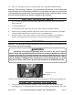
Generator Setup and Cable Connections 1. Place the Generator outdoors where it will be used. This should be on a flat surface and away from flammable materials. Do not allow the Generator to get wet. If used indoors, the area must be well ventilated to allow dissipation of exhaust fumes. 2. Fill the Gas Tank (outdoors) with up to seven gallons of unleaded gasoline. Do not top-off tank. 3. Add 40 oz. of oil to the Engine by removing either Dip Stick, and adding through its hole.
The Engine should start. Try again if it does not start. Refer to the Robin Subaru® Operator’s Manual under Troubleshooting if problems persist. Let the engine run for five minutes to warm up. 7. Push in the Choke Button. 8. Begin to turn on the connected appliances. The Engine governor will regulate the throttle automatically depending on the electrical load applied to the generator. If electricity to one of the outlets stops, it could be that the circuit was overloaded.
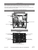
Parts List Part 1 2 3 5 6 7 10 11 12 13 14 15 16 17 18 19 22 23 24 25 26 27 Code # EH410GE 31227 30010102 30060802 15051079 30050202 15190240 45040103 15170101 30070102 15050104 15050101 10160102 70130202 60130703 60020206 60020304 60160703 60150718 60150713 60150725 60030109 Description GA ENGINE, 13.
Assembly Drawing PLEASE READ THE FOLLOWING CAREFULLY THE MANUFACTURER AND/OR DISTRIBUTOR HAS PROVIDED THE PARTS DIAGRAM IN THIS MANUAL AS A REFERENCE TOOL ONLY. NEITHER THE MANUFACTURER NOR DISTRIBUTOR MAKES ANY REPRESENTATION OR WARRANTY OF ANY KIND TO THE BUYER THAT HE OR SHE IS QUALIFIED TO MAKE ANY REPAIRS TO THE PRODUCT OR THAT HE OR SHE IS QUALIFIED TO REPLACE ANY PARTS OF THE PRODUCT.
Wiring Diagram Note: Only a licensed electrician should perform electrical repairs on this generator. Black White Black Green SKU 91377 For technical questions, please call 1-800-444-3353.
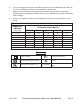
SCHEMATIC DRAWING RE-STARTER SWITCH WITH GFCI E D 5 7 D 6 4 9 3 F 1 B 2 A B 11 12 C G 10 Parts List Item QTY Description A 1 Inlet 20A Assembly of Cable & Terminals B 1 Inlet 30A 125/250V C 1 Inlet 30A 129 Blue D 2 Re-starter 20A Red E 1 Re-starter 25A 125/250V F 1 Wiring Harness Black G 1 Wiring Type 125 Cable of Caliber 12 White 200 Cable of Caliber 12 Black 105 Cable of Caliber 12 Green Black 65 Cable of Caliber 12 Red Black 55 Cable