Owner’s Manual & Safety Instructions Save This Manual Keep this manual for the safety warnings and precautions, assembly, operating, inspection, maintenance and cleaning procedures. Write the product’s serial number in the back of the manual near the assembly diagram (or month and year of purchase if product has no number). Keep this manual and the receipt in a safe and dry place for future reference. 212, 346 and 420 cc Horizontal Engines Using an engine indoors CAN KILL YOU IN MINUTES.
Table of Contents SAFETY Specifications.............................................. 2 Safety.......................................................... 3 Setup........................................................... 6 Operation..................................................... 8 Maintenance............................................... 14 Troubleshooting.......................................... 18 Warranties.................................................. 20 Parts Lists and Diagrams...........
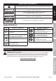
WARNING SYMBOLS AND DEFINITIONS This is the safety alert symbol. It is used to alert you to potential personal injury hazards. Obey all safety messages that follow this symbol to avoid possible injury or death. SAFETY Indicates a hazardous situation which, if not avoided, will result in death or serious injury. Indicates a hazardous situation which, if not avoided, could result in death or serious injury. Indicates a hazardous situation which, if not avoided, could result in minor or moderate injury.
Set up Precautions SAFETY 1. Gasoline fuel and fumes are flammable, and potentially explosive. Use proper fuel storage and handling procedures. Do not store fuel or other flammable materials nearby. 4. Set up and use only on a flat, level, well‑ventilated surface. 2. Have multiple ABC class fire extinguishers nearby. 6. Use only lubricants and fuel recommended in the Specifications chart of this manual. 3. Operation of this equipment may create sparks that can start fires around dry vegetation.
22. Keep the equipment, engine, and surrounding area clean at all times. 23. Use the equipment, accessories, etc., in accordance with these instructions and in the manner intended for the particular type of equipment, taking into account the working conditions and the work to be performed. Use of the equipment for operations different from those intended could result in a hazardous situation. 24. Do not operate the equipment with known leaks in the engine’s fuel system. 25.
Set Up Read the ENTIRE IMPORTANT SAFETY INFORMATION section at the beginning of this manual including all text under subheadings therein before set up or use of this product. SAFETY SETUP TO PREVENT SERIOUS INJURY: Operate only with proper spark arrestor installed. Model 68120: The emission control system for this engine is warranted for standards set by the U.S. Environmental Protection Agency. For warranty information, refer to the last pages of this manual.
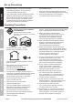
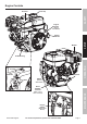
Engine Controls Fuel Cap SAFETY Air Filter Engine Switch (Electric Start Models) Muffler SETUP Starter Handle Throttle Dipstick Choke Fuel Valve Starter OPERATION Oil Drain Plug (Electric Start Models) Serial Number Location MAINTENANCE (Write on front cover of manual.) Engine Switch (Manual Start Models) Horizontal Engines For technical questions, please call 1-800-520-0882.
Operation Read the ENTIRE IMPORTANT SAFETY INFORMATION section at the beginning of this manual including all text under subheadings therein before set up or use of this product. SAFETY Pre-Start Checks Inspect engine and equipment looking for damaged, loose, and missing parts before set up and starting. If any problems are found, do not use equipment until fixed properly.
Checking and Filling Fuel 1. Clean the Fuel Cap and the area around it. 2. Unscrew and remove the Fuel Cap. 3. If needed, fill the Fuel Tank to about 1 inch under the fill neck of the Fuel Tank with 87 octane or higher unleaded gasoline. Note: Do not use gasoline containing more than 10% ethanol (E10). Do not use E85 ethanol. Note: Do not use gasoline that has been stored in a metal fuel container or a dirty fuel container.
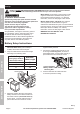
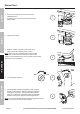
Manual Start SAFETY 1. To start a cold engine, move the Choke to the CHOKE position. To restart a warm engine, leave the Choke in the RUN position. 1 CHOKE RUN 2. Open the Fuel Valve. SETUP 2 3. Slide the Throttle or Speed Control Lever to 1/3 away from the SLOW position (the “turtle”). Note: Some tools have a Speed Control Lever located elsewhere on the tool which functions the same as the Throttle. Use the Speed Control Lever in place of the Throttle when the tool is so equipped.
6 SAFETY 6. Allow the Engine to run for several seconds. Then, if the Choke lever is in the CHOKE position, move the Choke Lever very slowly to its RUN position. Note: Moving the Choke Lever too fast could stall the engine. CHOKE RUN IMPORTANT: Allow the engine to run at no load for five minutes with no load after each start‑up so that the engine can stabilize. 7. Adjust the Throttle as needed. 8. Break-in Period: a. Breaking-in the engine will help to ensure proper equipment and engine operation. b.
Electric Start (if equipped) SAFETY 1. To start a cold engine, move the Choke to the CHOKE position. To restart a warm engine, leave the Choke in the RUN position. 1 CHOKE RUN SETUP 2 2. Open the Fuel Valve. 3. Slide the Throttle or Speed Control Lever to 1/3 away from the SLOW position (the “turtle”). OPERATION Note: Some tools have a Speed Control Lever located elsewhere on the tool which functions the same as the Throttle.
5 SAFETY 5. Allow the Engine to run for several seconds. Then, if the Choke lever is in the CHOKE position, move the Choke Lever very slowly to its RUN position. Note: Moving the Choke Lever too fast could stall the engine. CHOKE RUN IMPORTANT: Allow the engine to run at no load for five minutes with no load after each start‑up so that the engine can stabilize. 6. Adjust the Throttle as needed. 7. Break-in Period: a. Breaking-in the engine will help to ensure proper equipment and engine operation. b.
Maintenance WARNING SAFETY TO PREVENT SERIOUS INJURY FROM ACCIDENTAL STARTING: Turn the Power Switch of the equipment to its “OFF” position, wait for the engine to cool, and disconnect the spark plug cap before performing any inspection, maintenance, or cleaning procedures. TO PREVENT SERIOUS INJURY FROM EQUIPMENT FAILURE: Do not use damaged equipment. If abnormal noise, vibration, or excess smoking occurs, have the problem corrected before further use. Follow all service instructions in this manual.
Checking and Filling Fuel Engine Oil Change WARNING! TO PREVENT SERIOUS INJURY FROM FIRE: Fill the fuel tank in a well-ventilated area away from ignition sources. If the engine is hot from use, shut the engine off and wait for it to cool before adding fuel. Do not smoke. CAUTION! Oil is very hot during operation and can cause burns. Wait for engine to cool before changing oil. 1. Clean the Fuel Cap and the area around it. 4.
Air Filter Element Maintenance 1. Remove the air filter cover and the air filter elements and check for dirt. Clean or replace as described below. 2. Cleaning: SAFETY • For “paper” filter elements: To prevent injury from dust and debris, wear ANSI-approved safety goggles, NIOSH‑approved dust mask/respirator, and heavy-duty work gloves. In a well-ventilated area away from bystanders, use pressurized air to blow dust out of the air filter. If this does not get the filter clean, replace it.
Storage WARNING! TO PREVENT SERIOUS INJURY FROM FIRE: Drain the fuel tank in a well-ventilated area away from ignition sources. If the engine is hot from use, shut the engine off and wait for it to cool before draining fuel. Do not smoke. a. Place a funnel leading to a proper gasoline container below the carburetor. Sediment Cup (some engines) Drain Plug b. Remove the drain bolt from the bottom of the carburetor bowl and allow the fuel to drain. b. Clean out area around spark plug.
Troubleshooting Possible Causes Engine will not start FUEL RELATED: 1. No fuel in tank or fuel valve closed. 2. Choke not in CHOKE position, cold engine. 3. Gasoline with more than 10% ethanol used. (E15, E20, E85, etc.) SAFETY Problem Probable Solutions 9. Clogged Fuel Filter. FUEL RELATED: 1. Fill fuel tank and open fuel valve. 2. Move Choke to CHOKE position. 3. Clean out ethanol rich gasoline from fuel system. Replace components damaged by ethanol. Use fresh 87+ octane unleaded gasoline only.
5. Incorrect compression. Engine stops suddenly 1. Low oil shutdown. 2. Fuel tank empty or full of impure or low quality gasoline. 3. Defective fuel tank cap creating vacuum, preventing proper fuel flow. 4. Faulty magneto. 5. Disconnected or improperly connected spark plug cap. 1. Check wire connections. 2. Re-gap or replace spark plug. 3. Replace spark plug cap. 4. Use only fresh 87+ octane unleaded gasoline. Do not use gasoline with more than 10% ethanol (E15, E20, E85, etc.). 5.
Warranties Limited 90 Day Warranty SAFETY Harbor Freight Tools Co. makes every effort to assure that its products meet high quality and durability standards, and warrants to the original purchaser that this product is free from defects in materials and workmanship for the period of 90 days from the date of purchase.
5. Component parts which are not scheduled for replacement as required maintenance or are scheduled only for regular inspection to the effect of “repair or replace as necessary” are warranted for the warranty period. Any warranted part which is scheduled for replacement as required maintenance is warranted for the period of time up to the first scheduled replacement point for that part.
Parts Lists and Diagrams 68120 212cc Parts List SAFETY Part SETUP OPERATION MAINTENANCE 1 2 3 4 5 6 7 8 9 10 11 12 13 14 15 16 17 18 19 20 21 22 23 24 25 26 27 28 29 30 31 32 33 34 35 36 37 38 39 40 41 42 43 44 45 46 47 48 49 50 Description Gasket, Cylinder Head Cover Asm., Cylinder Head Gasket, Cylinder Head Cover Tube, Breather Bolt Stud Stud Stud Pin Bolt, Cylinder Head Plug, Spark Head Asm., Cylinder Crankcase Asm. Sensor, Engine Oil Gear Asm.
Horizontal Engines 5 5 5 5 For technical questions, please call 1-800-520-0882.
68121 212cc Parts List Part SAFETY SETUP OPERATION MAINTENANCE 1 2 3 4 5 6 7 8 9 10 11 12 13 14 15 16 17 18 19 20 21 22 23 24 25 26 27 28 29 30 31 32 33 34 35 36 37 38 39 40 41 42 43 44 45 46 47 48 49 50 51 52 53 54 Description Gasket, Cylinder Head Cover Asm., Cylinder Head Gasket, Cylinder Head Cover Tube, Breather Bolt Stud Stud Stud Pin Bolt, Cylinder Head Plug, Spark Head Asm., Cylinder Crankcase Asm. Sensor, Engine Oil Gear Asm.
Horizontal Engines 5 5 5 5 For technical questions, please call 1-800-520-0882.
68136 346cc Parts List Part SAFETY SETUP OPERATION MAINTENANCE 1 2 3 4 5 6 7 8 9 10 11 12 13 14 15 16 17 18 19 20 21 22 23 24 25 26 27 28 29 30 31 32 33 34 35 36 37 38 39 40 41 42 43 44 45 46 47 48 49 50 51 52 53 54 55 56 Description Gasket, Cylinder Head Cover Asm., Cylinder Head Gasket, Cylinder Head Cover Tube, Breather Bolt Asm., Cylinder Head Cover Stud Stud Pin Bolt, Cylinder Head Plug, Spark Head Asm., Cylinder Crankcase Asm.
Horizontal Engines 5 For technical questions, please call 1-800-520-0882.
68306 420cc Parts List Part SAFETY SETUP OPERATION MAINTENANCE 1 2 3 4 5 6 7 8 9 10 11 12 13 14 15 16 17 18 19 20 21 22 23 24 25 26 27 28 29 30 31 32 33 34 35 36 37 38 39 40 41 42 43 44 45 46 47 48 49 50 51 52 53 54 55 56 57 58 59 60 61 62 Page 28 Description Gasket, Cylinder Head Cover Asm., Cylinder Head Gasket, Cylinder Head Cover Tube, Breather Bolt Asm., Cylinder Head Cover Stud Stud Pin Bolt, Cylinder Head Plug, Spark Head Asm., Cylinder Crankcase Asm.
Horizontal Engines 123 5 84 84 82 83 80 80 124 For technical questions, please call 1-800-520-0882.
Mounting Hole Diagrams Note: Not to scale. SAFETY ITEM 68120 / 68121 212cc 6.38 in. / 162mm 2.6 in. / 66mm 3.17 in. / 80.5mm 2.97 in. / 75.5mm 1.6 in. / 40.5mm SETUP ITEM 68136 346cc and ITEM 68306 420cc 7.72 in. / 196mm 4.13 in. / 105mm 3.39 in. / 86mm 4.06 in. / 103mm OPERATION MAINTENANCE Page 30 For technical questions, please call 1-800-520-0882.
Power Take-Off Diagrams Note: Not to scale. SAFETY ITEM 68120 / 68121 212cc 2.43 in. / 61.7mm 5/16-24UNF 0.67 in. / 17mm Ø0.75 in. / 19.05mm 0.64 in. / 16.36mm 0.1875 in. / 4.78mm 5/16-24UNF 1.79 in. / 45.5mm Ø3.625 in. / 92mm 4.17 in. / 106mm SETUP 4x5/16-24UNF ITEM 68136 346cc and ITEM 68306 420cc (30°) (30°) 3.48 in. / 88.5mm Ø5.75 in. / 146mm Ø5 in. / 127mm Ø1 in. / 25.4mm Ø1.17 in. / 29.7mm 0.36 in. / 9.13mm 3/8-24UNF 0.25 in. / 6.35mm 1.1 in. / 28mm 2.2 in. / 56mm 2.84 in.
3491 Mission Oaks Blvd. • PO Box 6009 • Camarillo, CA 93011 • (800) 520-0882 www.harborfreight.