
Product manual


Page 4 For technical questions, please call 1-800-444-3353. Item 69650
Setup - Before Use:
Read the ENTIRE IMPORTANT SAFETY INFORMATION section
at the beginning of this manual including all text under
subheadings therein before set up or use of this product.
Note: For additional information regarding the parts listed in the following pages,
refer to Parts List and Assembly Diagram on page 7.
Turn vehicle’s ignition OFF, set parking brake, and chock wheels before assembly.
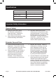
Assembly
1. With the short end of the L-Extension
(4) facing up, slide the long end into
the receiver hitch (not included).
2. Insert an Angled Pin (2) through
the hitch and L-Extension (4).
3. Secure with a R-Pin (3) through
the hole in the Angled Pin (2).
4. Slide the Warning Flag (5) onto
the remaining Angled Pin (2).
5. The T-Support (1) has five holes
to change the height. Line up the
hole on the T-Support (1) with the
desired hole on the L-Extension (4).
6. Insert the Angled Pin (2) with
the Warning Flag through
T-Support and L-Extension.
7. Secure with the remaining R-Pin (3).
8. Pull out on the L-Extension and
T-Support to make sure they
are properly locked in place.
Functions
Note: Lowest setting shown.
Figure A: Components
L-Extension
T-Support
Receiver Hitch hole
Height holes
Angled Pin
R-Pin