
User guide

Chapter 3 - Installation
3-7
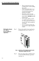
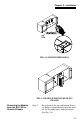
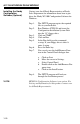
FIG. 3-6 MODULE WITH DOOR OPEN
Step 2. Install the cable and
connector so it allows
the module door to be shut.
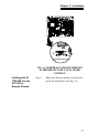
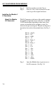
Step 3. There is a bracket (not shown) that allows
you
to use a tie wrap to secure the cable to
the module.
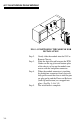
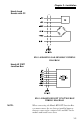
Step 4. With the plug oriented correctly
(See the
pin-out diagram above), plug the I/O male
connector into the I/O connector at the
front of the module.
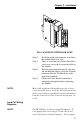
Step 5. Check to be sure that the connector is
com
pletely plugged in before operating
the module.
NOTE: Most of the problems with modules are due to loose
connections. Be sur
e to check the I/O connection first
in the event you have a problem receiving information
from the load cells or if the relays do not operate cor-
rectly.
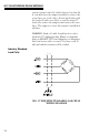
Load Cell Wiring
Diagrams
NOTE: The HI 1746 has two factory installed jumpers. If
your
application is not using C2 load cells do not
remove the factory installed jumpers . If your appli-