
User guide


Chapter 4 - Setup
4-7
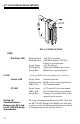
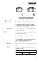
FIG. 4-2 PRIMARY AND REMOTE
COMMUNICATION DIAGRAM
Command Word
Enc
oding
You may write up to 7 words at a time to either the
Logical O file or the Logical M0 file. Word #0 of the
8 word output file is used to specify where words 1-7
go in either the logical O or M0 file, is called the
“Command Word”. Word #0 of the I file will always
be a copy of the “Command Word”.
Bits 15 & 14 11 = write 0 to 7 words to the logical M0 file,
Read 7
words from the M1 file.
NOTE: You need to run any command through M files before
pr
evious writes take effect.
01 = write 0 to 7 words to the logical O file, Read
(co
nfigured) I
10 = configure 0 to 7 words for the I file return, con-
figure 7 words to read from Logical I file.
00 = the configured I file returned.
Bits 8-13 Number of words to write to the logical M0
or logical
O file.
Bits 0-7 Offset (in words) in the logical
M0 or logical O file
where the write begins.
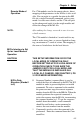
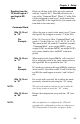
Command Word - 16 bits
Bits 15-14 Bits 13-8 Bits 7-0