
Instruction Manual


i
●
●
●
●
●
Contents
Contents
● ● ● ● ●
CONTENTS ........................................................................................................... I
CHAPTER 1 OVERVIEW ..................................................................................... 1
About Hardy Manuals ................................................................................................................................. 1
HI 1756 nDF Overview ................................................................................................................................. 1
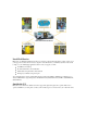
Typical Applications ................................................................................................................................... 2
Features and Capabilities ............................................................................................................................. 2
CHAPTER 2 SPECIFICATIONS .......................................................................... 5
Basic Specifications ....................................................................................................................................... 5
General ........................................................................................................................................................ 5
Environmental Requirements ...................................................................................................................... 6
Pending Approvals ...................................................................................................................................... 6
CHAPTER 3 INSTALLATION .............................................................................. 7
Unpacking ...................................................................................................................................................... 7
Installing the HI 1756 nDF ........................................................................................................................... 7
Allen-Bradley ControlLogix Processor or Remote Rack ............................................................................ 7
A ControlLogix Chassis .............................................................................................................................. 7
Removing the Module from the Chassis ..................................................................................................... 8
Installing the Module I/O Connector ........................................................................................................... 8
Load Cell Wiring Diagrams ......................................................................................................................... 9
HI 1756 1DF Valve wiring diagram ............................................................................................................. 9
Hardy HI 215IT Junction Box ................................................................................................................... 10
CHAPTER 4 CONFIGURATION ........................................................................ 11
Power Check ................................................................................................................................................ 11
LEDs ......................................................................................................................................................... 11
Dot Matrix Display .................................................................................................................................... 12
Setting Up Communications ....................................................................................................................... 12
Configuring the HI 1756-nDF Dispenser Filler Module in the RSLogix 5000 for ControlLogix with the
HI 1756-nDF Module Add on Profile ....................................................................................................... 12
Linking the PLC with the HI 1756-nDF Dispenser Filler Control Module ............................................... 15
Overview of Operation ................................................................................................................................ 16
DINT Configuration Parameters used in Flow Rate Control .................................................................... 18
REAL Configuration Parameters used in Flow Rate Control .................................................................... 19
DINT Configuration Parameters used in Auto-Preact ............................................................................... 22
REAL Configuration Parameters used in Auto-Preact .............................................................................. 22
Status Values used in Auto-Preact function .............................................................................................. 23
Assembly Object Instances ......................................................................................................................... 25
First Word – 0: Command Number .......................................................................................................... 27