HI 1769-WS & HI 1769-2WS WEIGH SCALE MODULE OPERATION AND INSTALLATION MANUAL Corporate Headquarters 9440 Carroll Park Drive San Diego, CA 92121 Phone: (858) 278-2900 FAX: (858) 278-6700 Web-Site: http://www.hardysolutions.com Hardy Process Solutions Document Number: 0596-0282-01 Rev T Copyright 2011-2013 Hardy Process Solutions, All Rights Reserved. Printed in the U.S.A.
Local Field Service Hardy has over 200 field technicians in the U.S., and more positioned throughout the world to assist you in your support needs. We also have factory engineers who will travel to your facility anywhere in the world to help you solve challenging applications.
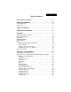
Table of Contents Table of Contents HI 1769-WS & HI 1769-2WS - - - - - - - - - - - - - - - - - - - - 1-1 WEIGH SCALE MODULE - - - - - - - - - - - - - - - - - - - - - 1-1 Local Field Service - - - - - - - - - - - - - - - - - - - - - - - - - 1-2 Outside the U.
HI 1769-WS/HI 1769-2WS WEIGH SCALE MODULE Load Cell Excitation- - - - - - - - - - - C2 Calibration Output - - - - - - - - - - Environmental Requirements - - - - - - - - Temperature Coefficient - - - - - - - - Operating Temperature Range - - - - - Storage Temperature Range - - - - - - Humidity Range - - - - - - - - - - - - Approvals - - - - - - - - - - - - - - - Digital Voltmeter - - - - - - - - - - - - Optional Equipment- - - - - - - - - - - - - 1756 RTA (Remote Termination Assembly RTA Cable Assemblies - -
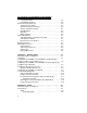
Table of Contents OK Module Status LED - - - - - - - - - - - - - - - - - - - 4-2 Setting Up Communications Between the MicroLogix 1500 Processor and the HI 1769-WS & HI 1769-2WS Weigh Scale Modules - - - - - - - - - - - - - - - - - - - - - - - - - - - - - - 4-3 Alternative Setup Procedures - - - - - - - - - - - - - - - - - - - - 4-5 Configuring the HI 1769-WS in RSLogix 500 for MicroLogix 1500 - - - - - - - - - - - - - - - - - - - - - - - - 4-5 Configuring the HI 1769-WS in RSLogix 5000 for CompactLogix - 4
HI 1769-WS/HI 1769-2WS WEIGH SCALE MODULE Electrical - - - - - - - - - - - - - - - - - - - - - - - - - - - - - -6-6 Mechanical Stability and Configuration Settings - - - - - - - - - - -6-7 INDEX iv
Table of Illustrations Table of Illustrations HI 1769-WS & HI 1769-2WS1-1 WEIGH SCALE MODULE1-1 TABLE OF CONTENTS1-I TABLE OF ILLUSTRATIONS1-I OVERVIEW1-1 CHAPTER 2 - SPECIFICATIONS2-1 CHAPTER 3 - INSTALLATION3-1 POSITIONING THE MODULE FOR INSTALLATION3-3 CONNECTOR UNLOCK POSITION3-3 CONNECTOR IN LOCKED POSITION3-4 MODULE CONNECTOR INSTALLED3-6 MODULE CONNECTOR REMOVED FOR EASIER CABLING3-7 RAIL FASTENERS IN RETRACTED POSITION3-8 RAIL FASTENERS IN THE CLOSED POSITION3-9 INDUSTRY STANDARD LOAD CELLS WIRING
HI 1769-WS/HI 1769-2WS WEIGH SCALE MODULE I/O CONFIGURATION DIALOG BOX4-6 I/O CONFIGURATION DIALOG BOX4-7 SELECTING COMPACTBUS LOCAL4-8 SELECT MODULE TYPE/SELECTING 1769 MODULE/GENERIC4-8 MODULE PROPERTIES DIALOG BOX/CONFIGURATION/SIZE/0 WORDS49 MODULE PROPERTIES DIALOG BOX/CONFIGURATION/SIZE/48 WORD S4-9 CONTROLLER TAGS/SLOT 14-15 CHAPTER 5 - CALIBRATION5-1 PROPERLY INSTALLED LOAD CELL W/NO BINDING5-2 MILLIVOLTS/WEIGHT SCALE5-4 CHAPTER 6 - TROUBLESHOOTING6-1 MECHANICAL INSPECTION6-2 LOAD SHARING AND LOAD S
Chapter 1 - Overview CHAPTER 1 - OVERVIEW A BRIEF DESCRIPTION OF CHAPTER 1 This manual provides the user and service personnel with a description of the specifications, installation, setup, configuration, operation, communication, maintenance, and troubleshooting procedures for the Hardy HI 1769-WS & HI 1769-2WS Compact and Micro Logix I/O Weigh Scale Modules that mount on the Allen-Bradley® CompactLogix™ and MicroLogix™ 1500 platform.
HI 1769-WS/HI 1769-2WS WEIGH SCALE MODULE NOTE: Hardy Process Solutions bases all procedures with the assumption that the user has an adequate understanding of Allen-Bradley ControlLogix®. In addition the user should understand process control and be able to interpret ladder logic instructions necessary to generate the electronic signals that control your application(s).
Chapter 1 - Overview can be used for a wide variety of process weighing applications such as batching, blending, filling/dispensing, check weighing, force measurement, level by weight and weight rate monitoring. The analog to digital converter in the weigh module controller updates one hundred (100) times per second and is capable of 8,388,608 counts of display resolution.
HI 1769-WS/HI 1769-2WS WEIGH SCALE MODULE detects the quantity of load sensors in the system. All calibrations can be performed via ladder logic. IT ® INTEGRATED TECHNICIAN™ is a system diagnostics utility. For full functionality the weigh system should include an HI 215IT series junction box. Full IT functionality allows the operator to rapidly troubleshoot a weighing system.
Chapter 1 - Overview 1. 2. 3. Disconnects the controller and engages an internal reference signal to see if the problem is within the instrument. Disconnects the load sensors and engages an internal (in the junction box) reference signal to see if the cable between the instrument and the Junction Box is causing the problem. Reads the weight of each load sensor to see if the load sensor might be causing the problem.
HI 1769-WS/HI 1769-2WS WEIGH SCALE MODULE 1-6
Chapter 2 - Specifications CHAPTER 2 - SPECIFICATIONS A Brief Description of Chapter 2 Chapter 2 lists the specifications for the HI 1769-WS & HI 1769-2WS Weigh Scale Modules. Specifications are listed for the standard instrument and for optional equipment. The specifications listed are designed to assist in the installation, operation and troubleshooting of the instrument. All service personnel should be familiar with this section before attempting an installation or repair of this instrument.
HI 1769-WS/HI 1769-2WS WEIGH SCALE MODULE Common-Mode Voltage Range 2.5VDC maximum (with respect to earth ground) Bus Input Voltage 5 VDC Bus Current Load <0.5 Amp at 5 VDC Bus Power Load < 5W at 5 VDC C2 Calibration Input Isolation from digital section 1000 VDC minimum. Cable lengths 500 feet maximum of C2 authorized cable 250 feet maximum of C2 authorized cable (Maximum of 4 load sensors) with IT Junction box.
Chapter 2 - Specifications Optional Equipment 1756 RTA (Remote Termination Assembly Hardy Part # -RTA (HI-1769-XX-RTA if ordered separately) Remote Termination supports two (2) separate HI 1769-WS or HI 1769-2WS weigh scale modules. Unit includes DIN rail mounting for 35mm x 15mm DIN rail. RTA Cable Assemblies Hardy Part # -C6 (HI 1769-XX-C6) • Cable Length: 6 ft. (1.525 meters) from the single channel module to the RTA.
HI 1769-WS/HI 1769-2WS WEIGH SCALE MODULE Parameter Default Setting ZeroTrackEnable False 0 ZeroTolerance 10.0 lbs 10.0 AutoZeroTolerance 10.0 lbs 10.0 MotionTolerance 5.0 lbs 5.0 Table 2-1: Default Parameters EMI Suppression Core 2-4 Cable Diameter .250 inches Max. (6.4 mm Max) Supression Frequencies Up to 500 MHz Cable Types • • Physical Dimensions Width - .705 inches (17.9 mm) Height - .724 inches (18.39 mm) Length - 1.272 inches (32.
Chapter 3 - Installation CHAPTER 3 - INSTALLATION A Brief Description of Chapter 3 All information contained in Chapter 3 pertains to unpacking, cabling, interconnecting, configuration and installing the Weigh Scale Module. Alternatives to any procedures contained or implied in this chapter are not recommended. It is very important that the user and service personnel be familiar with the procedures contained in this chapter, before installing or operating the Weigh Scale module.
HI 1769-WS/HI 1769-2WS WEIGH SCALE MODULE Installing the HI 1769-WS or HI 1769-2WS to an Allen-Bradley CompactLogix or MicroLogix 1500 Processor WARNING ELECTROSTATIC DISCHARGE MAY DAMAGE SEMICONDUCTOR COMPONENTS. DO NOT TOUCH THE CONNECTOR PINS AND OBSERVE THE FOLLOWING HANDLING PRECAUTIONS: • • • • • • Installing the HI 1769-WS or HI 1769-2WS onto the CompactLogix and MicroLogix 1500 Bank 3-2 Step 1. Wear an approved wrist-strap grounding device when handling the module.
Chapter 3 - Installation Lever A Lever B Module A Module B FIG. 3-1 POSITIONING THE MODULE FOR INSTALLATION Step 2. Pull Lever B back to the unlock position. FIG.
HI 1769-WS/HI 1769-2WS WEIGH SCALE MODULE Step 3. Step 4. Gently slide the HI 1769-WS or HI 17692WS module onto the other module. In our example we connected two Hardy HI 1769-WS Weigh Modules. When you have the modules aligned, press Lever B towards Module A to fasten the connector to Module A. (See Fig. 3-3) FIG. 3-3 CONNECTOR IN LOCKED POSITION Step 5. The installation is comple.
Chapter 3 - Installation Single Channel Pin 1 Pin 3 Pin 5 Pin 7 Pin 9 Pin 11 Pin 13 Pin 15 Pin 17 Shield1 C2-1 C2+1 Exc-1 Sen-1 Sig-1 Sig+1 Sen+1 Exc+1 Dual Channel Pin 1 Pin 3 Pin 5 Pin 7 Pin 9 Pin 11 Pin 13 Pin 15 Pin 17 Step 1. Step 2. Step 3. Shield1 C2-1 C2+1 Exc-1 Sen-1 Sig-1 Sig+1 Sen+1 Exc+1 Pin 2 Pin 4 Pin 6 Pin 8 Pin 10 Pin 12 Pin 14 Pin 16 Pin 18 Shield2 C2-2 C2+2 Exc-2 Sen-2 Sig-2 Sig+2 Sen+2 Exc+2 Open the Module door to gain access to the I/O connector. (See Fig.
HI 1769-WS/HI 1769-2WS WEIGH SCALE MODULE Step 4. To install the connector reverse steps 2 & 3. FIG.
Chapter 3 - Installation FIG. 3-5 MODULE CONNECTOR REMOVED FOR EASIER CABLING Step 5. Step 6. Install the cable so it allows the module door to close. Check to be sure that the wires are securely connected before operating the module. NOTE: Most of the problems with modules are due to loose connections. Be sure to check the I/O connection first in the event you have a problem receiving information from the load cells. Installing the HI 1769WS on a Din Rail Step 1.
HI 1769-WS/HI 1769-2WS WEIGH SCALE MODULE Rail Fasteners FIG. 3-6 RAIL FASTENERS IN RETRACTED POSITION Step 2. Step 3. Step 4. Step 5. 3-8 Place the module on the DIN rail. While holding the module in place, press the two rail fasteners towards the center of the module until they both snap into place. (See Fig. 3-7) The module is now securely fastened to the DIN Rail. To remove the module from the DIN rail reverse steps 2 & 3 above.
Chapter 3 - Installation FIG.
HI 1769-WS/HI 1769-2WS WEIGH SCALE MODULE Load Cell Wiring Diagrams Industry Standard Load Cells FIG.
Chapter 3 - Installation Hardy Load Sensor with C2 FIG. 3-9 HARDY LOAD SENSOR/C2 WIRING DIAGRAM WARNING: HARDY PROCESS SOLUTIONS RECOMMENDS THAT YOU DO NOT CUT YOUR ADVANTAGE® OR ADVANTAGE LITE® LOAD SENSOR CABLE, BECAUSE YOUR C2® ACCURACY WILL BE AFFECTED AND THE WARRANTY VOIDED. HI 1769 Remote Terminal Assembly (HI 1769-XX-RT) Provides connection points between the cable assembly from the HI 1769-WS module and the individual wires from the junction box(es) or load sensor(s). (See Fig.
HI 1769-WS/HI 1769-2WS WEIGH SCALE MODULE FIG. 3-10 REMOTE TERMINAL ASSEMBLY 59mm (2.3") FIG. 3-11 RTA DIN RAIL MOUNT RTA Cable Assembly 3-12 • Six (6) foot cable and schematic that connects to the HI 1769-WS module. (See Figs.
Chapter 3 - Installation FIG. 3-12 RTA CABLE ASSEMBLY - HI 1769WS FIG. 3-13 RTA CABLE SCHEMATIC - HI 1769WS • Six (6) foot cable that connects to the HI 17692WS. (See Figs. 3-14 & 3-15) FIG.
HI 1769-WS/HI 1769-2WS WEIGH SCALE MODULE FIG. 3-15 RTA SCHEMATIC HI 1769-2WS EMI Suppression Core Installation (Prt. #2547-0013) NOTE: For CE requirements you will need to install an EMI suppression core around the multi-strand portion of the RTA cable. (See Fig. 3-12 & 3-14) Install one suppression core for the single channel model and two (2) suppression cores for the dual channel model. Step 1. Step 2. Step 3.
Chapter 3 - Installation Latch FIG. 3-16 EMI SUPPRESSION CORE Step 4. Open the core until it is wide enough to enclose all the strands of wire. (See Fig. 317) FIG. 3-17 SUPPRESSION CORE OPEN Step 5. Place all the wire strands in the core and gently close the core until it snaps shut. (See Fig.
HI 1769-WS/HI 1769-2WS WEIGH SCALE MODULE FIG. 3-18 SUPPRESSION CORE INSTALLED Hardy HI 215IT Junction Box FIG. 3-19 HARDY HI 215IT JUNCTION BOX WIRING DIAGRAM NOTE: 3-16 When connecting the Hardy HI 215IT Junction Box you must remove the two factory installed jumpers 17&15 and 7&9 on the module install sense lines except when installing four (4) wire non C2 load cells.
Chapter 4 - Setup CHAPTER 4 - SETUP A Brief Description of Chapter 4 All information contained in Chapter 4 pertains to firmware and software settings to prepare the module controller for calibration and operation. Alternatives to these procedures either explicit or implied, contained in this section are not recommended. It is very important that the user and service personnel be familiar with the procedures contained in this chapter, before going through the setup procedures.
HI 1769-WS/HI 1769-2WS WEIGH SCALE MODULE FIG. 4-2 MODULE LEDS HI 1769-2WS DUAL CHANNEL LEDS The module has a Scale LED and an OK LED associated with it. The LEDs may be green, red or off. They may be steady, Fast Flashing (5 Hertz) of Slow Flashing (1 Hertz) Scale Data LEDs Steady Green Running (Normal) Slow Flashing Green Error No Calibration Steady Red Error ERRORADFAILURE (hardware induced) status bit is set. Flashing Red Read AD Convert Error.
Chapter 4 - Setup Setting Up Communications Between the MicroLogix 1500 Processor and the HI 1769-WS & HI 17692WS Weigh Scale Modules NOTE: On the side of the module you will see a label that reads either Firmware REV A or Firmware REV B,C,D etc. Both setup procedures are the same except for the Connection Parameters/Extra Data Length. For REV A the setting is 0. For all other REVs the setting is 48.
HI 1769-WS/HI 1769-2WS WEIGH SCALE MODULE Step 3. Step 4. Click on the “Read IO Config” button. (See Fig. 4-4) The “Read IO Configuration from Online Processor” dialog box appears. (See Fig. 4-5) RSLogix 500 automatically reads the I/O information and enters them into the configuration text fields. (See Fig. 4-4) FIG. 4-4 READ I/O CONFIGURATION FROM ONLINE PROCESSOR DIALOG BOX 4-4 Step 5. The HI 1769-WS I/O is configured and ready to communicate with the MicroLogix 1500 Processor. Step 6.
Chapter 4 - Setup FIG. 4-5 CONNECTION/CONFIGURATION - 48 Alternative Setup Procedures Configuring the HI 1769-WS in RSLogix 500 for MicroLogix 1500 To set up communication between the MicroLogix 1500 Processor and the Weigh Scale Module you will need to do the following in RSLogix 500: Step 1. Step 2. Under Project, click on the + next to controller. (See Fig. 4-6) Click on I/O Configuration. The I/O Configuration dialog box appears. (See Fig.
HI 1769-WS/HI 1769-2WS WEIGH SCALE MODULE FIG. 4-6 EXPANDING CONTROLLER FIG. 4-7 I/O CONFIGURATION DIALOG BOX Step 3. Step 4. Step 5. 4-6 From the I/O Configuration dialog box, under the “#” column heading, click on #1 or the next open slot number available. (See Fig. 4-8) In the Current Cards Available, double click on “Other - Requires I/O Type Card ID” under the Description column heading.
Chapter 4 - Setup On some PLC platforms it may be necessary to enter the Vendor ID, the Product Type, the Product Code, Input/Output Words and Extra Data Length. See below: • HARDY_VENDOR_ID 0x102 (258 decimal) • HARDY_PRODUCT_TYPE 0x54 (100 decimal) • HARDY_PRODUCT-CODE 5 • Input Words - 32 • Output Words - 32 • Extra Data Length - 0 for Firmware REV A or 48 for later Firmware REVs. Step 6. Step 7. Click on the “Apply.” button. “OTHER” appears under the Part # column heading. (See Fig.
HI 1769-WS/HI 1769-2WS WEIGH SCALE MODULE FIG. 4-9 SELECTING COMPACTBUS LOCAL Step 2. Right click on “CompactBus Local”. A dialog box appears. Step 3. Click on “New Module”. The “Select Module Type” dialog box appears. (See Fig. 4-10) FIG.
Chapter 4 - Setup Step 4. Step 5. Step 6. From the Select Module Type dialog box, scroll down the list until you find the 1769 Module - Generic Module. Double click on the 1769 Generic Module. Click on the OK button. The Module Properties dialog box appears. (See Figs. 4-11 & 12) FIG. 4-11 MODULE PROPERTIES DIALOG BOX/CONFIGURATION/SIZE/0 WORDS FIG. 4-12 MODULE PROPERTIES DIALOG BOX/CONFIGURATION/SIZE/48 WORDS Step 7. Click in the Name Text box. Enter a descriptive name for the module.
HI 1769-WS/HI 1769-2WS WEIGH SCALE MODULE Step 8. Step 9. Step 10. Step 11. Step 12. Step 13. Step 14. Click in the Description Text Box. Type in a description of the module. Click on the down arrow to the right of Comm Format to open the pull down list. Click on Data-INT to select the Comm Format. Use the up or down arrows to the right of Slot, to select the slot number for the installed HI 1769-WS or HI 1769-2WS. Under Connection Parameters/Input use the up or down arrows to select 32 words.
Chapter 4 - Setup • • • • • • • Name #define ERRORADCONVERT 0x0001 #define ERRORADFAILURE 0x0002 #define STATUSINMOTION 0x0040 #define ERRORNOCAL 0x0080 #define ERROREEPROMWRITE 0x0100 // an error occurred when writing to nonvolatile memory #define NVRDEFAULTED 0x0200 // set if SETDEFAULTPARAMS command was given #define STATUSCHANENABLED 0x8000 // set if channel is enabled Description Default ChanActive 16 bit integer, set to 1 if the channel is active, 0 if not active 1 Metric 16 bit integer wh
HI 1769-WS/HI 1769-2WS WEIGH SCALE MODULE Name Description Default NumAverages 16 bit integer, 1-255 20 ZeroTrackEnable 16 bit integer 0 turns auto-zero tracking off 1 turns auto-zero tracking on 0 AutoZeroTolerance 32 bit weight value, format determined by value of Metric Parameter 10.0 lbs. ZeroTolerance 32 bit weight value, format determined by value of Metric Parameter 10.0 lbs.
Chapter 4 - Setup The configuration data is sent from the PLC to the HI 1769-WS module at power-up. The module uses these parameters provided that: 1. 2. The parameters are in the correct range. Illegal values will be rejected. The “CopyConfig” word (0 for channel 0, 24 for channel 1) is set to 1.
HI 1769-WS/HI 1769-2WS WEIGH SCALE MODULE Parameter Offset (In Words) Data Type Ch0CalLowWeight 14 REAL or INT Ch0ROCtimebase 16 INT Ch0CopyCal 17 INT Ch0calzerocount 18 DINT Ch0CalHighCount 20 DINT Ch0Spare2 22 INT Ch0Spare3 23 INT Ch1CopyConfig 24 INT Ch1ChanActive 25 INT Ch1Metric 26 INT Ch1Waversaver 27 INT Ch1NumAverages 28 INT Ch1ZeroTrackEnable 29 INT Ch1AutoZeroTolerance 30 REAL or INT Ch1MotionTolerance 32 REAL or INT Ch1ZeroTolerance 34 REAL or IN
Chapter 4 - Setup parameters in the form above. When you expand the slot you selected for the these parameters they will look like the following: Local:1:C.Data[0] Local:1:C.Data[1] Local:1:C.Data[2] Local:1:C.Data[3] ...and so on These correspond directly to the parameters in the table above. (See Fig. 4-13) FIG. 4-13 CONTROLLER TAGS/SLOT 1 Commands About Commands The first 16 words are reserved for Channel 0. The second 16 words are reserved for Channel 1.
HI 1769-WS/HI 1769-2WS WEIGH SCALE MODULE input table is called the command STATUS. Normally, a 0 value of STATUS means that the command completed OK and a non-zero status indicates some kind of error. Command Operation Step 1. Step 2. Step 3. To start a command, place the command number into the first word of the output table. The Input Table contains the response for that command.
Chapter 4 - Setup Command Table Required Output Table Values Written by User (PLC) Input Table Response From Weigh Scale NOCMD (no command) 0 Give this command to read weight from the module.
HI 1769-WS/HI 1769-2WS WEIGH SCALE MODULE Required Output Table Values Written by User (PLC) Input Table Response From Weigh Scale WRITEMETRIC 3 Writes the Metric Parameter. Does NOT save the value of the metric parameter to non-volatile memory.
Chapter 4 - Setup Command WRITEPARAM0 0x67 Write a block of parameters: To write a single parameter: Step 1. Do a READPARAM0 command. Step 2. Copy the parameters read to the output. Step 3. Change the parameter value Step 4. Set the command word.
HI 1769-WS/HI 1769-2WS WEIGH SCALE MODULE Required Output Table Values Written by User (PLC) Input Table Response From Weigh Scale READPARAM0 0x69 Read a parameter block. Weight values are formatted according to the Metric parameter.
Chapter 4 - Setup Command STABILITYTEST 0x6B Switch in a specified signal in place of the normal load cell signal. With an ITJBOX, 4 individual load cell signals, or a reference signal on the JBOX may be switched in. Without an IT-JBOX, only an onboard reference signal may be switched in. Giving any other command after STABILITYTEST causes the unit to return to normal operation.
HI 1769-WS/HI 1769-2WS WEIGH SCALE MODULE TESTRESULTS 0x6C Report the results of a previous INTEGRATED TECHNICIAN test. No new test is performed O:0-0x6C O:1-15 (unused) I:0x6C I:1 = return to zero test result, bit coded: • Bits set to 1 indicate nonreturn to zero. • Bit 0 = combined weight • Bits 1-4 (JBOX only) indicate non-return to zero on a individual JBOX sensor. I:2-15 are all INTEGER values. • Millivolt/volt readings have 4 decimal places. • Load Cell resistance has zero decimal places.
Chapter 4 - Setup WEIGHSYSTEST 0x6D Perform an INTEGRATED TECHNICIAN test.
HI 1769-WS/HI 1769-2WS WEIGH SCALE MODULE READC2SERIALNUM 0x70 Read data from a C2 sensor. The C2SEARCH command must be performed before this command is done. O:0 = 0x70 O:1 = SENSOR NUMBER (0-7) I:0 = 0x70 I:1 = COMMAND STATUS I:2-9 = Serial Number I:10 = Sensitivity, LSW I:11 = Sensitivity, MSW I:12 = Capacity, LSW I:13 = Capacity, MSW NOTE: Sensitivity is an integer, with 4 decimal places and dimensions of millivolts per volt. Capacity is an integer with 0 decimal places, with units of pounds.
Chapter 4 - Setup Setting The Zero Tolerance Value Sets the range of weights so that the Zero Command works, as an offset of the calibrated Zero. Setting the Auto Zero Tolerance Value When the Auto Zero Tolerance is entered, and Auto Zero Tracking is enabled, any weight within the entered tolerance of zero and not in motion, will cause the display to automatically read zero. NOTE: There is a short time delay (at least 1 second) before the AutoZero Triggers.
HI 1769-WS/HI 1769-2WS WEIGH SCALE MODULE 4-26
Chapter 5 - Calibration CHAPTER 5 - CALIBRATION A Brief Description of Chapter 5 Chapter 5 pertains to the calibration procedures for the HI 1769-WS and HI 1769-2WS Weigh Scale Modules. Alternatives to any procedures either implied or explicitly contained in this chapter are not recommended. In order for the Weigh Module to work properly, it must be calibrated prior to operation. It is recommended that the module calibration be verified periodically or when not in use for extended periods of time.
HI 1769-WS/HI-1769-2WS WEIGH SCALE MODULE a. b. c. A load cell must be mounted in such a way that 100% of the load (Vessel w/ Contents) is vertically passed through a load cell. (See Fig. 5-1) Check to see that nothing is binding the load cell. This means that nothing is draped across the scale/vessel or the load cell, such as a hose, electrical cord, tubes, or other objects.
Chapter 5 - Calibration a. b. c. d. e. The Weigh Module is designed to supply 5 VDC excitation to as many as four (4) 350 Ohm load cells/points. The expected output from each load cell/point depends on the mV/V rating of the load cell/point and the weight. For example, a 2mV/V load cell/point will respond with a maximum of 10 mVDC at full weight capacity of the system which includes the weight of the vessel and the weight of the product as measured by the load cell/point.
HI 1769-WS/HI-1769-2WS WEIGH SCALE MODULE FIG. 5-2 MILLIVOLTS/WEIGHT SCALE f. Based on the example, the operating range for this scale is 5-10 mVDC with a 500 pound weight range. Understand that after zeroing the instrument, the 0 reading refers to the zero reference point and not absolute 0 mVDC or absolute 0 weight. NOTE: Load cell/point measurements are checked with a digital volt meter at the J1 connector on the front of the module or by using INTEGRATED TECHNICIAN with the HI 215IT Junction Box.
Chapter 5 - Calibration • • Step 3. scale, the ladder logic display should read 120 or some value over 100. If the ladder logic display reads 100 pounds and a 20 pound load is placed on the vessel or scale and the reading is 80 pounds, the reading is going in the wrong direction and indicates some problem with the system. If the ladder logic display is reading improperly or shows no change there is something wrong with the setup.
HI 1769-WS/HI-1769-2WS WEIGH SCALE MODULE Hard Calibration Hard Calibration Ladder Logic Example Hard Calibration is the traditional method of calibration that uses test weights. Hardy recommends that the test weights total 80 to 100% of the scale capacity. Step 1. Check to be sure that the parameters have been setup for your weighing process. (See Chapter 4, Setup) We have provided a Ladder Logic example explaining how to set the weigh process parameters.
CHAPTER 6 - Troubleshooting CHAPTER 6 - TROUBLESHOOTING A Brief Description of Chapter 6 All the information in Chapter 6 pertains to the troubleshooting and resolution of operating problems that may occur. All maintenance personnel and users should be familiar with Chapter 6 before attempting to repair the HI 1769-WS. Scale LED is Flashing Red Solution: Check all the connections to be sure they are securely fastened. Reinstall if any appear to be loose. Mechanical Inspection See Fig.
HI 1769-WS/HI 1769-2WS MANUAL 1) 2) 3) 4) 5) 6) 7) 8) All pipes and conduits flexible? Mechanically isolated from ladders and connecting structures? 1) 2) 3) Keep flexures on the horizontal Vertical flexures should be avoided Do not use flexures to correct for misaligned piping Do not use hose flexures to make right angle bends Non-flexed piping should have an unsupported horizontal run using a ratio of 36 times it's diameter.
CHAPTER 6 - Troubleshooting Load Sharing and Load Sensor Checkout See Figure 6-2 NOTE: On balancing load cells, the overall objective is to insure each load cell sees a positive millivolt reading. When weight is evenly applied, all load cells signals should increase the same amount. NOTE: Insure the millivolt distribution is equal enough so not to overload any one load cell.
HI 1769-WS/HI 1769-2WS MANUAL 1) 2) Does the mV signal increase in a positive direction. If you receive a negative results, check if load cell is mounted correctly. a) The arrow goes with the direction of force. b) If there isn't an arrow, you must manually verify the correct direction. A negative reading indicates the load cell is upside down. c) Load cells in tension will not reflect a negative reading if install upside down.
CHAPTER 6 - Troubleshooting Guidelines for Instabilities on Formerly Operating Systems See Figure 6-3 Check for Electrical Stability OK ? No B1 Yes Check for Mechanical Stability Yes OK ? No B2 Yes Check for Mechanical Stability OK ? No B3 Yes Contact Hardy Instruments Ser vice Center FIG.
HI 1769-WS/HI 1769-2WS MANUAL Electrical See Figure 6-4 B1 B1.1 B1.2 B1.3 B1.4 B1.5 B1.6 Electrical Physical Grounding All common equipment share a common ground point. Keep the ground cable length to earth ground as short as possible. Install a new ground rod if the cable length is excessive. Cable Cust or breaks in the load cell insulation allow moisture to wick into the cable and load points. This can setup stray capacitance charges and allow ground currents to exist.
CHAPTER 6 - Troubleshooting Mechanical Stability and Configuration Settings See Figure 6-5 Mechanical Stability Vessel When inpspecting a vessel keep in mind, the Center of Gravity (COG) should be low and centered equally over all the load cells. Insure the load is directly over or under the load point to avoid side-loadin. Make sure there isn’t any side loading from piping or external forces. Install flexures on all piping to insure a free floating vessel.
HI 1769-WS/HI 1769-2WS MANUAL 6-8
Index Index Symbols “dead” loads 1-3 “OTHER” 4-7 “The Button” 1-3 Numerics 16 bit integer 4-10 1756 RTA (Remote Termination Assembly 2-3 1769 Generic Module 4-9 2 Channel HI 1769-2WS 2-1 32 bit float 4-10 32 bit IEEE float 4-10 32 bit integer 4-10 32 bit integers 4-10 350 Ohm load cells/points 5-3 5 VDC excitation 5-3 A A Brief Description of Chapter 1 1-1 A Brief Description of Chapter 2 2-1 A Brief Description of Chapter 3 3-1 A Brief Description of Chapter 4 4-1 A Brief Description of Chapter 5 5-1 A Br
HI 1769-WS/HI 1769-2WS MANUAL Allen-Bradley’s RS Logix 5000 4-1 analog to digital converter 1-3 Approvals 2-2 Auto Zero Tolerance 1-5 Auto Zero Tracking 1-5, 4-25 Averages 2-1 B Backplane Current Load 2-2 Backplane Input Voltage 2-2 Backplane Power Load 2-2 Before signing 3-1 Binding 5-1 C C2 Calibration 5-5 C2 Calibration Input 2-2 C2 Calibration Output 2-2 C2 Calibration Using Ladder Logic 5-5 C2 load sensors 5-5 C2® Calibration 1-3 cable 3-7 cable cover 3-14 Cable lengths 2-2 calibrated electronically 1
Index Common-Mode Rejection 2-1 Common-Mode Voltage Range 2-2 CompactBus Local 4-8 CompactLogix 3-2 CompactLogix Processor 4-7 Configuration 1-2 configuration data 4-13 Connection Parameters dialog bo 4-4 Connection Parameters/Configuration 4-10 Connection Parameters/Extra Data Length 4-3 Connection Parameters/Input 4-10 Connection Parameters/Output 4-10 ControlLogix I/O 1-2 Conversion Rate 2-1 Customer Support Department 1-1 D damaged load sensors 1-4 Data-INT 4-10 Dead Load 5-3 Default Parameters 2-3 Des
HI 1769-WS/HI 1769-2WS MANUAL EXC & SIG Outputs 5-2 F Finish 4-10 Firmware REV A 4-3 Firmware REV B,C,D etc.
Index Installing the HI 1756-WS (-2WS) 3-2 Installing the HI 1769-WS on a Din Rail 3-6, 3-7 Installing the Module I/O Connector 3-4 integrated communication 1-1 Integrated Technician 5-4 Integrated Technician™ 1-4 IT 1-4 L ladder logic 1-1 ladder logic display 5-4 Ladder Logic example 5-5, 5-6 LEDS 4-1, 4-2 Lever B 3-3 Load Cell Excitation 2-2 Load Cell Wiring Diagrams 3-10 Load Cell/Point Input/Output Measurements 5-2 Load Check 5-4 Load Sharing and Load Sensor Checkout 6-3 loose connections 3-7 M Maximum
HI 1769-WS/HI 1769-2WS MANUAL mV/V rating 5-3 mV/V readings 1-4 N Name Text box 4-9 NEVER touch the connector pins 3-2 Non-Linearity 2-1 O OK Module Status LED 4-2 open the suppression core 3-14 Operating Temperature Range 2-2 Optional Equipment 2-3 over sizing of load cells/sensors 1-3 Overview 1-2 P Parameters for the HI 1756-WS (-2WS) Module 4-15 Possible COMMAND STATUS Values 4-16 Pre-Calibration Procedures 5-1 R Read IO Config” button 4-4 Read IO Configuration from Online Processor” dialog box 4-4 REA
Index S Sample Programs 5-5 Scale Data LEDs 4-2 Scale LED is Flashing Red 6-1 Select Module Type 4-8 Setting the Auto Zero Tolerance Value 4-25 Setting the Metric Parameter 4-24 Setting the Motion Tolerance Value 4-24 Setting the Number of Readings Averages 4-25 Setting the Span Weight Value 4-25 Setting the WAVERSAVER Value 4-25 Setting The Zero Tolerance Value 4-25 Setting Up Communications Between the MicroLogix 1500 Processor and the HI 1769-WS Weigh Scale Module 4-3 single module 1-2 Specifications 1-
HI 1769-WS/HI 1769-2WS MANUAL Weighing System Tests 1-4 wrist-strap grounding device 3-2