
Manual

Chapter 3 - Installation
3-5
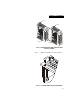
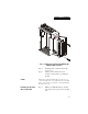
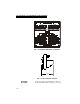
Step 1. Open the Module door to gain access to
the I/O connector. (See Fig. 3-4)
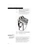
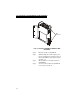
Step 2. To make the cable connections easier you
can remove the connector from the mod
-
ule. To remove the connector, use a phil-
lips screw driver and remove the two (2)
phillips pan head screws that fasten the
connector to the module. (See Fig. 3-5)
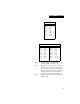
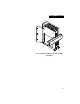
Step 3. Gently pull the connector off of the board
in the module.
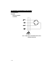
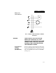
Single Channel
Pin 1 Shield1
Pin 3 C2-1
Pin 5 C2+1
Pin 7 Exc-1
Pin 9 Sen-1
Pin 11 Sig-1
Pin 13 Sig+1
Pin 15 Sen+1
Pin 17 Exc+1
Dual Channel
Pin 1 Shield1
Pin 3 C2-1
Pin 5 C2+1
Pin 7 Exc-1
Pin 9 Sen-1
Pin 11 Sig-1
Pin 13 Sig+1
Pin 15 Sen+1
Pin 17 Exc+1
Pin 2 Shield2
Pin 4 C2-2
Pin 6 C2+2
Pin 8 Exc-2
Pin 10 Sen-2
Pin 12 Sig-2
Pin 14 Sig+2
Pin 16 Sen+2
Pin 18 Exc+2