
Manual


Chapter 4 - Setup
4-13
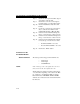
The configuration data is sent from the PLC to the HI
1769-WS module at power-up. The module uses these
parameters provided that:
1. The parameters are in the correct range. Ille-
gal values will be rejected.
2. The “CopyConfig” word (0 for channel 0, 24
for channel 1) is set to 1.
• INT parameters are 2 byte integers
• DINT parameters are 4 byte integers
• REAL parameters are 4 byte IEEE
floating point numbers
NOTE: Parameters labeled “REAL or DINT” will be inter-
preted as floating point or integer according to the
value of the “METRIC” parameter of the channel. If
bit 6 (0x40) of METRIC is set the parameter is float
-
ing point. If bit 6 is not set, it is a fixed point integer,
with 0-7 decimal places as determined the first 3 bits
of the METRIC parameter.
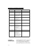
Parameter
Offset (In
Words)
Data Type
Ch0CopyConfig 0 INT
Ch0ChanActive 1 INT
Ch0Metric 2 INT
Ch0Waversaver 3 INT
Ch0NumAverages 4 INT
Ch0ZeroTrackEnable 5 INT
Ch0AutoZeroTolerance 6 REAL or INT
Ch0MotionTolerance 8 REAL or INT
Ch0ZeroTolerance 10 REAL or INT
Ch0SpanWeight 12 REAL or INT